
Instruction manual


INTUITY Messaging Solutions Release 4
MAP/5P Maintenance
585-310-186
Issue 3
October 1997
Replacing Other Components
Page 7-37Power Supply Replacement
7
Inserting a Power Supply
To insert the power supply, do the following:
1. Remove the spare power supply unit from the shipping carton.
NOTE:
Keep the package and all ESD-protective wrapping to return the
defective unit. Re-use of the original replacement unit packaging is
necessary to meet the manufacturer’s warranty.
2. Verify the input AC voltage selection switch, located on the chassis side
close to the button edge, is in the correct position.
The switch is a slide type. Printed text on the surface indicates the input
voltage requirements, either 115 or 230 Volts. The correct position for
systems installed in the United States is 115 volts.
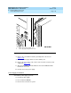
3. Install the power supply unit into the chassis and align the screw holes.
4. Install the four screws on the chassis rear area that secure the power
supply unit (Figure 7-15
).
5. Attach the power supply DC output connectors to the motherboard (Figure
7-15).
NOTE:
These connectors are keyed.
6. Attach the connector to the cartridge tape drive (Figure 7-15
).
7. Attach the connector to the diskette drive (Figure 7-15
).
8. Attach the connector to the Hard Disk Drive 1, if provided
(Figure 7-15
).
If Hard Disk Drive 1 is not installed, dress this lead back out of the way to
reduce cable congestion.
9. Attach the connector to Hard Disk Drive 0 (Figure 7-15
).
10. Dress the power switch cable around to the front of the MAP/5P
(Figure 7-17
).