
Instruction manual


INTUITY Messaging Solutions Release 4
MAP/5P Maintenance
585-310-186
Issue 3
October 1997
Replacing Other Components
Page 7-28Motherboard Replacement
7
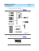
Figure 7-12. Motherboard Cable Connections
10. Attach the turbo LED connector to CN19 (Figure 7-12
).
11. Attach the power LED connector to CN19 (Figure 7-12
).
12. Attach the remote maintenance circuit card reset cable to CN30
(Figure 7-12
).
Re-assembling the MAP/5P
To re-assemble the MAP/5P, do the following:
1. Replace the riser card. See “Riser Card Installation
” above for the
procedure.
2. Replace the circuit cards. See “Installing a Circuit Card
” in Chapter 5,
‘‘Replacing or Installing Circuit Cards’’.”
3. Replace the dress cover. See “Replacing the Dress Cover
” in Chapter 4,
‘‘Getting Inside the Computer’’,” for this procedure.
1. RMB reset cable connector (pins 1 and 2 of CN30)
2. Reset switch connector (pins 19 and 20 of CN19)
3. Turbo LED connector (pins 12 and 13 of CN19)
4. Power LED connector (pins 3,4, and 5 of CN19)