
Instruction manual


INTUITY Messaging Solutions Release 4
MAP/5P Maintenance
585-310-186
Issue 3
October 1997
Replacing Other Components
Page 7-21Memory Replacement
7
4. Repeat Steps 1 through 3 for the SIMM located in the SIMM1 socket.
5. Continue with the next procedure, “SIMM Installation
.”
SIMM Installation
To install the SIMMs, you must:
■ Insert the SIMMs.
■ Re-assemble the MAP/5P.
■ Restore the Lucent INTUITY system.
Inserting the SIMMs
To insert the SIMMs, do the following:
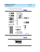
1. Install a SIMM in the SIMM1 socket by positioning the it at approximately a
45-degree angle with respect to the motherboard.
All SIMMs are keyed to prevent them from being inserted incorrectly.
2. Push down at that angle until the SIMM is reseated into the SIMM carrier.
3. Snap the SIMM into place by rotating it to an upright position.
The metal snap lock on the ends of the connector for the SIMM will be
forced open and then lock when in the upright position.
4. Ensure the connector guide pins are seated into the clearance holes
provided at each end of the SIMM.
When properly seated, the guides should be fully extended into the circuit
card clearance holes.
5. Repeat Steps 1
through 4 to install a SIMM in the SIMM2 socket.
Re-assembling the MAP/5P
To re-assemble the MAP/5P, do the following:
1. Replace the circuit cards in the bottom three slots. See “Installing a Circuit
Card” in Chapter 5, ‘‘Replacing or Installing Circuit Cards’’.”
2. Replace the dress cover. See “Replacing the Dress Cover
” in Chapter 4,
‘‘Getting Inside the Computer’’,” for this procedure.
Restoring the Lucent INTUITY System
To restore the Lucent INTUITY system, do the following:
1. Restore power to the MAP/5P. See “Restoring Power to the MAP/5P
” in
Chapter 4, ‘‘Getting Inside the Computer’’
,” for the procedure.
2. Verify the Lucent I
NTUITY system operation by placing a call to a user.