
Instruction manual


INTUITY Messaging Solutions Release 4
MAP/5P Maintenance
585-310-186
Issue 3
October 1997
Replacing Other Components
Page 7-15Fan Replacement
7
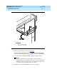
Accessing the Circuit Card Cage Fan
To access the circuit card cage fan, do the following:
1. Remove the dress cover. See “Removing the Dress Cover
” in Chapter 4,
‘‘Getting Inside the Computer’’,” for this procedure.
2. Remove the protective aluminum screen which holds the circuit card cage
fan in the chassis.
Extracting the Circuit Card Cage Fan
To extract the circuit card cage fan, do the following:
1. Lift the circuit card cage fan out of the chassis.
2. Unplug the 12-VDC power lead connector.
!
CAUTION:
Do not operate the MAP/5P for any length of time without the circuit
card cage fan installed and operational.
3. Continue with the next procedure, “Circuit Card Cage Fan Installation.”
Circuit Card Cage Fan Installation
To install the circuit card cage fan, you must:
■ Insert the circuit card cage fan.
■ Re-assemble the MAP/5P.
■ Restore the Lucent INTUITY system.
Inserting the Circuit Card Cage Fan
To insert the circuit card cage fan, do the following:
1. Attach the 12-VDC connector to the circuit card cage fan.
2. Place the circuit card cage fan in the MAP/5P chassis.
NOTE:
Make sure the air flow is directed into the MAP/5P chassis. There is
an air flow direction arrow on the fan.
Re-assembling the MAP/5P
To re-assemble the MAP/5P, do the following:
1. Replace the aluminum screen.
2. Replace the dress cover. See “Replacing the Dress Cover
” in Chapter 4,
‘‘Getting Inside the Computer’’,” for this procedure.