
Instruction manual


INTUITY Messaging Solutions Release 4
MAP/5P Maintenance
585-310-186
Issue 3
October 1997
Replacing Other Components
Page 7-14Fan Replacement
7
Fan Replacement
!
CAUTION:
Observe proper electrostatic discharge precautions when you handle
computer components. Wear an antistatic wrist strap that touches your bare
skin and connect the strap cable to an earth ground. See “Protecting
against Damage from Electrostatic Discharge” in Chapter 4, ‘‘Getting Inside
the Computer’’.
The MAP/5P contains the following fans that provide cooling inside the unit:
■ Power supply fan
■ Circuit card cage fan
■ CPU fan
The power supply fan is located inside the power supply and is
not
serviceable.
Never attempt repairs to this fan. If it fails, you must replace the entire power
supply. See “Power Supply Replacement
” below for more information.
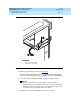
Circuit Card Cage Fan Replacement
The circuit card cage fan is located in front of the card cage, behind the dress
cover (Figure 7-1
). The circuit card cage fan forces air flow through the MAP/5P
chassis, across the circuit cards.
Circuit Card Cage Fan Removal
To remove the circuit card cage fan, you must:
■ Remove the Lucent INTUITY system from service.
■ Access the circuit card cage fan.
■ Extract the circuit card cage fan.
Removing the Lucent INTUITY System from Service
To remove the Lucent INTUITY system from service, do the following:
1. Verify that the replacement equipment is on site and appears to be in
usable condition, with no obvious shipping damage.
2. Stop the voice system. See “Stopping the Voice System
” in Chapter 3,
‘‘Common System Procedures’’, for the procedure.
3. Shut down the voice system. See “Shutting Down the Lucent
Intuity
System” in Chapter 3, ‘‘Common System Procedures’’, for the procedure.
4. Remove the incoming power. See “Removing Power from the MAP/5P
” in
Chapter 4, ‘‘Getting Inside the Computer’’
, for this procedure.