
Instruction manual


INTUITY Messaging Solutions Release 4
MAP/5P Maintenance
585-310-186
Issue 3
October 1997
Replacing Other Components
Page 7-12Diskette Drive Replacement
7
7. Remove the diskette drive from the peripheral frame.
!
CAUTION:
Handle the diskette drive with care. The spindle motor, stepping
motor, and printed circuit board are located on the bottom of the
diskette drive. Do not place any force or strain on these components
and do not touch the surface of the diskette drive printed circuit
board.
8. Place the diskette drive assembly, with the printed circuit board facing up,
on an ESD-protected surface.
9. Continue with the next procedure, “Diskette Drive Installation
.”
Diskette Drive Installation
To install the diskette drive, you must:
■ Insert the diskette drive.
■ Re-assemble the MAP/5P.
■ Restore the Lucent INTUITY system.
Inserting the Diskette Drive
To insert the diskette drive, do the following:
1. Remove the new diskette drive from its ESD-protective wrapping.
NOTE:
Keep the package and all ESD-protective wrapping to return the
defective unit. Re-use of the original replacement unit packaging is
necessary to meet the manufacturer’s warranty.
2. Attach the diskette drive to the peripheral frame using the four screws
removed in Step 6
of “Extracting the Diskette Drive” above.
NOTE:
Pay close attention to the location of the screws in both the
peripheral frame and the diskette drive. If the screws are returned to
a different position, the diskette drive may protrude from the chassis
too far or be recessed into the chassis too much.
3. Attach the power cable to the diskette drive.
4. Attach the diskette cable to the diskette drive.
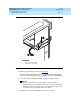
5. Place the front of the peripheral frame into the MAP/5P.
6. Align the peripheral frame so that the bracing lip on the MAP/5P chassis is
below the guide on the peripheral frame (Figure 7-6
).