
Instruction manual


INTUITY Messaging Solutions Release 4
MAP/5P Maintenance
585-310-186
Issue 3
October 1997
Replacing or Installing Circuit Cards
Page 5-47Installing a Remote Maintenance Circuit Card, Version 2
5
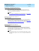
The system displays the View Installed Hardware window
(Figure 5-2
).
Figure 5-34. View Installed Hardware Window
2. Verify that the system has identified the new circuit card.
Attaching External Cables to the Remote Maintenance Circuit Card
To connect the remote maintenance circuit card, do the following:
1. Connect the modem line to the remote maintenance circuit card and the
switch.
2. Connect the external UPS line to the modem.
3. Connect the EMI suppression cable to the remote maintenance circuit
card and the switch.
4. Restore the system to service.
5. Call the remote maintenance center and inform them that you have
installed the remote maintenance circuit card.
The remote maintenance center will log in through the remote
maintenance circuit card and:
■ Set the passwords
■ Verify the product ID
> View Installed Hardware
> System Verification
> Customer/Services Administration