
Instruction manual


INTUITY Messaging Solutions Release 4
MAP/5P Maintenance
585-310-186
Issue 3
October 1997
Replacing or Installing Circuit Cards
Page 5-45Installing a Remote Maintenance Circuit Card, Version 2
5
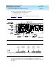
MAP/5P Cable Connections.
The remote maintenance circuit card connects to
CN30 which is located on the motherboard. Figure 5-32
shows the location of
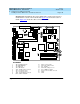
CN30. Figure 5-33
shows the cable connection to CN30.
Figure 5-32. Motherboard Jumper Locations
1. JP5 - flash BIOS function
2. JP6 - BIOS ROM type
3. JP1 - BIOS type
4. JP2 - LED function
5. JP15 - standby power connector
6. JP4 - second-level cache
7. JP3 - second-level cache
8. JP30 - external battery connector
9. JP16 - software shutdown
10. JP42 - L2 cache mode
11. JP43 - CPU voltage for I/O
12. JP7 - regulator
13. JP44 - CPU voltage for core
14. JP11 - SMM/reset switch
15. JP14 - power-on switch connector
16. CN30
17. CN19