
Instruction manual


INTUITY Messaging Solutions Release 4
MAP/5P Maintenance
585-310-186
Issue 3
October 1997
Replacing or Installing Circuit Cards
Page 5-44Installing a Remote Maintenance Circuit Card, Version 2
5
The cable code (printed on the cable) is as follows:
■ ED5P 208-30 G 32 – fan status cable
■ ED5P 208-30 GR 31 – reset cable
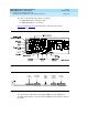
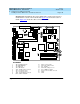
Figure 5-30
and Figure 5-31 show the cable connectors on the remote
maintenance circuit card.
Figure 5-30. RMB connectors (top view)
Figure 5-31. RMB connectors (side view)
You can dress the cables above or below the RMB. Use your judgement to
determine the best way to connect to the board with the least amount of strain on
the cables.
ON
1
cdr2edg LJK 041597
UPS
connector
Fan status
connector
BEC
enable
switch
Platform
reset
connector
Factory
use only