
Instruction manual


INTUITY Messaging Solutions Release 4
MAP/5P Maintenance
585-310-186
Issue 3
October 1997
Replacing or Installing Circuit Cards
Page 5-42Installing a Remote Maintenance Circuit Card, Version 2
5
Installing the New Remote Maintenance Circuit
Card
To install the new remote maintenance circuit card, you must:
■ Insert the circuit card
■ Attach cables to the circuit card
■ Restore the system
■ Verify the installation
Inserting the Circuit Card
To insert the new remote maintenance circuit card, do the following:
1. Remove the new circuit card from its ESD protective wrapping.
NOTE:
Keep the package and all ESD protective wrapping. If you must
return a card for repair, re-use of the replacement unit packaging is
necessary to meet the manufacturer’s warranty.
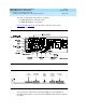
2. Make sure the BEC enable switch on the remote maintenance circuit card
is in the ON position (Figure 5-19
).
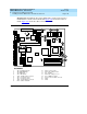
3. Holding the circuit card by its upper corners, slide the card into the
backplane connector slot position from which you removed the damaged
card.
Table 5-2
lists the correct slot for each platform.
4. Apply even pressure to both corners of the circuit card until it is locked
into the backplane.
5. Secure the circuit card faceplate into position by replacing the retaining
screw.
Table 5-2. Remote Maintenance Circuit Card Slot Locations
Platform Correct Slot
MAP/5P ISA Slot 2
MAP/40 Slot 9
MAP/40P ISA Slot 9
MAP/100 Slot 19
Continued on next page