
Instruction manual


INTUITY Messaging Solutions Release 4
MAP/5P Maintenance
585-310-186
Issue 3
October 1997
Replacing or Installing Circuit Cards
Page 5-41Installing a Remote Maintenance Circuit Card, Version 2
5
Replacing a Defective Remote Maintenance
Circuit Card
To replace a defective remote maintenance circuit card, you must:
■ Remove the defective remote maintenance circuit card
■ Install the new remote maintenance circuit card
■ Attach external cables to the remote maintenance circuit card
Removing the Defective Remote Maintenance
Circuit Card
To remove the defective remote maintenance circuit card, do the following:
1. Verify that the replacement equipment is on site and appears to be in
usable condition, with no obvious shipping damage.
NOTE:
Note all symptoms of failure and include this information with the
remote maintenance circuit card when it is returned.
2. If the system is in service, perform the following steps.
a. Stop the voice system.
b. Shut down the voice system.
3. Remove power from the computer.
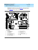
4. Access the circuit card cage.
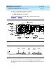
5. Locate the remote maintenance circuit card.
6. If there are ribbon cables attached to other cards which would impede the
removal of the card, disconnect them and place them to the side. Note
the connectivity of each cable.
7. Remove the retaining screw from the circuit card faceplate and save it.
8. Remove the circuit card from the backplane slot by gently pulling on each
corner of the card.
NOTE:
Make sure to install the replacement remote maintenance circuit
card in the same backplane slot.
9. Remove the circuit card from the chassis.
!
CAUTION:
Hold the circuit card carefully by the edges and place it on a
grounded mat.