
Instruction manual


INTUITY Messaging Solutions Release 4
MAP/5P Maintenance
585-310-186
Issue 3
October 1997
Replacing or Installing Circuit Cards
Page 5-32Circuit Card Settings
5
3. Remove the dress cover. See ‘‘Removing the Dress Cover’’ in Chapter 4,
‘‘Getting Inside the Computer’’, for power removal procedures.
4. Complete the procedures listed in ‘‘Inserting the Circuit Card’’
and
‘‘Re-assembling the MAP/5P’’
above.
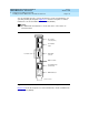
NOTE:
Make sure the BEC enable switch on the remote maintenance circuit
card is in the ON position (Figure 5-19
).
5. Connect the modem line to the remote maintenance circuit card and the
switch.
!
CAUTION:
Step 6 must be completed during the reboot of the system.
6. Disable COM2 by changing the
Serial Ports 16550 Compatible
UART 2
to
DISABLED
.
This setting is located in the CMOS advanced option settings for the CPU.
See ‘‘Verifying the CMOS Settings’’
in Chapter 7, ‘‘Replacing Other
Components’’, for the procedure.
7. Reboot the Lucent I
NTUITY system. See ‘‘Rebooting the System’’ in Chapter
3, ‘‘Common System Procedures’’, for the procedure.
8. Install the Remote Maintenance Circuit Card Software package. See
‘‘Installing the Remote Maintenance Circuit Card Software Package’’
above for the procedure.
9. Place the BEC enable switch on the remote maintenance circuit card in
the ON position (Figure 5-19
).
10. Press
.
11. Reboot the Lucent I
NTUITY system. See ‘‘Rebooting the System’’ in Chapter
3, ‘‘Common System Procedures’’, for the procedure.
12. Call the remote maintenance center and inform them that you have
installed the remote maintenance circuit card.
The remote maintenance center will log in through the remote
maintenance circuit card and:
■ Set the passwords
■ Verify the product ID
■ Verify the alarm destination
ENTER