
Instruction manual


INTUITY Messaging Solutions Release 4
MAP/5P Maintenance
585-310-186
Issue 3
October 1997
Replacing or Installing Circuit Cards
Page 5-31Circuit Card Settings
5
Replacing a Defective Remote Maintenance
Circuit Card
See ‘‘General Procedures’’ for procedures on remote maintenance circuit card
installation.
1. Complete the procedures listed in ‘‘Removing a Circuit Card’’
above for
the defective circuit card.
2. Complete the procedures listed in ‘‘Inserting the Circuit Card’’
and
‘‘Re-assembling the MAP/5P’’
above.
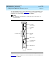
NOTE:
Make sure the BEC enable switch on the remote maintenance circuit
card is in the ON position (Figure 5-19
).
3. Connect the modem line to the remote maintenance circuit card and the
switch.
4. Connect the EMI suppression cable to the remote maintenance circuit
card and the switch.
5. Complete the procedures listed in ‘‘Restoring the Lucent
Intuity System to
Service’’ above.
6. Call your remote maintenance center and inform them that you have
replaced the remote maintenance circuit card.
The remote maintenance center will log in through the remote
maintenance circuit card and:
■ Set the passwords
■ Verify the product ID
■ Verify the alarm destination
■ Configure all parameters as specified by the Services Organization
Replacing a Modem with a Remote Maintenance
Circuit Card
See ‘‘General Procedures’’ for procedures on remote maintenance circuit card
installation.
1. If the system is in service, perform the following steps.
a. Stop the voice system. See ‘‘Stopping the Voice System’’
in Chapter
3, ‘‘Common System Procedures’’, for the procedure.
b. Shut down the voice system. See ‘‘Shutting Down the Lucent
Intuity
System’’ in Chapter 3, ‘‘Common System Procedures’’, for the
procedure.
2. Remove power from the MAP/5P. See ‘‘Removing Power from the MAP/5P’’
in Chapter 4, ‘‘Getting Inside the Computer’’
,for power removal
procedures.