Eicon 1530 WAN Router User’s Guide www.eicon.
Second Edition (December 2001) 206-391-02 Eicon, Eicon Networks, and Diva are either registered trademarks or trademarks of Eicon Networks Corporation. Microsoft, Windows, and Windows NT are either registered trademarks or trademarks of Microsoft Corporation in the United States and/or other countries. Adobe and Acrobat are either registered trademarks or trademarks of Adobe Systems Incorporated in the United States and/or other countries. Apple and Macintosh are trademarks of Apple Computer, Inc.
Contents Introduction .................................................................................................... 6 Overview ................................................................................................................................... 7 Package Contents..................................................................................................................... 8 Specifications..............................................................................................
Web Interface Settings Glossary ................................................................ 61 System Menu .......................................................................................................................... 62 Connection Menu.................................................................................................................... 63 Connection Menu > Connection Group (when protocol is set to PPP) ...................................
Command Line Interface ........................................................................... 106 Overview ............................................................................................................................... 107 General Commands.............................................................................................................. 108 Time and Date Commands ...................................................................................................
Introduction Overview ...................................................................................................................... 7 Package Contents ........................................................................................................ 8 Specifications ...............................................................................................................
Overview Thank you for purchasing the Eicon 1530 WAN Router. The Eicon 1530 is an intelligent Ethernet-to-WAN router that supports PPP, Frame Relay, and X.25 protocols. The Eicon 1530’s VHSI port can transfer data at speeds from 2400 bps to 2048 kbps, depending on the interface used. Hardware Features The Eicon 1530 features a 36-pin VHSI (Very High Speed Interface) port, that supports both V.24 and V.35 interfaces.
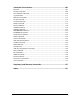
Package Contents Your package should contain the following: Eicon 1530 Power Adapter Ethernet Cable (Blue) Quickstart Guide CD-ROM VHSI cables are not included with your Eicon 1530. Cables can be ordered from Eicon Networks, or you can build your own (see the User’s Guide). Note: The blue cable is a straight-through Ethernet cable and is used to connect the Eicon 1530 to a network hub. To connect to a single computer, a crossover cable (sold separately) is required.
Specifications Hardware Features • • • • • • • VHSI (Very High Speed Interface) port, supports V.24 and V.35 interfaces Ethernet 10BaseT RJ45 port AUX port (DB9 V.24 serial interface) (currently unsupported) Power jack Hard Reset button Indicators lights Flash memory for convenient firmware upgrade (if available) VHSI Port (Synchronous) • 36-pin high-density D-type connector • Auto-detection of the following interface types: – V.24 (EIA RS232-C) – V.
LAN Protocol support • • • • • IP routing (dynamic and static) IP Network Address Translation (NAT) IP spoofing and packet filtering DHCP Server and DHCP Relay Agent BOOTP, TFTP, Telnet, ARP, and DNS Environmental Requirements • Operating temperature: 0°C to +50°C • Storage temperature: -20°C to +70°C • Operating humidity: 0 to 90% (non-condensing) Power Requirements • External AC wall mount adapter providing 9-15VDC/1A • Power consumption: 5 Watts maximum Warranty • Five years Certification • • • •
Setup System Requirements ............................................................................................... 12 Step 1: Connect the Cables ...................................................................................... 13 Step 2: Verify Computer TCP/IP Settings .............................................................. 14 Step 3: Log in to the Eicon 1530 .............................................................................. 15 Step 4: Modify VHSI Settings.....................
System Requirements Before you begin, review the system requirements, as outlined below. If you are connecting the Eicon 1530 directly to a computer, the following is required: • A 10Base-T Ethernet network interface card, properly installed and configured to use the TCP/IP protocol. A 100 Mbps Ethernet card can be used if the card supports auto-sensing. • TCP/IP communications protocol configured to obtain its IP address automatically (DHCP client), and not configured to use a DNS server.
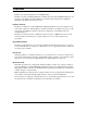
Step 1: Connect the Cables Leave your computer on when connecting the cables. Front of device VHSI Port Back of device Ethernet Port VHSI Light VHSI cable Blue Ethernet cable (straightthrough) Ethernet Lights Power Light Power Ethernet Hub Power adapter To modem or leased line 1. Connect the power adapter. The Power indicator light should turn green. Note: For more information on indicator lights, see Ports and Indicator Lights on page 29. 2. Connect your VHSI Cable.
Step 2: Verify Computer TCP/IP Settings The Eicon 1530 settings are changed via a series of web pages that reside on the Eicon 1530 itself. However, to access these pages, your TCP/IP settings must be configured appropriately, as described below. IP Address Recommendations • Set your Ethernet card to acquire its IP address dynamically if: – You are connecting the Eicon 1530 to a single computer. – You are installing on a LAN and wish to use the Eicon 1530 as your DHCP server.
Step 3: Log in to the Eicon 1530 Whenever you wish to change settings on the Eicon 1530, you must first log in, as shown below. 1. Launch your web browser and click ‘File’, ‘Open’. 2. Enter 192.168.1.1 as the web page to open. 3. Click ‘OK’. You should see the ‘Log in’ page. Note: If you do not see the ‘Log in’ page, see Troubleshooting on the following page. 4. Click the ‘Log in’ button. Note: By default there is no password. 5. The main menu should appear, as shown below.
Troubleshooting If you cannot access the ‘Log in’ page: • Verify that the Ethernet cable is connected properly. The green light at the top left of the Ethernet port should be on (see Ports and Indicator Lights on page 29 for more information). • Verify that your computer’s TCP/IP settings are configured according to your situation. As the Eicon 1530’s default IP address is 192.168.1.
Step 4: Modify VHSI Settings Once you have logged into the Eicon 1530 web interface, the first setting you should verify is the choice of protocol for the VHSI port (set to ‘X.25’ by default). The protocol should be selected first because all profile settings (which define particular connections) are deleted when the protocol is changed. About the Web Interface The Eicon 1530 settings are changed via web pages that reside on the Eicon 1530 itself.
Choosing a VHSI Protocol 1. From the Link List (the menu at the left of the screen), click on the small ‘+’ next to ‘VHSI Port’ to expand the VHSI Port group, then click the ‘Protocol’ link. ‘Protocol’ link 2. From the ‘Protocol’ drop-down menu, select a protocol. ‘Protocol’ drop-down menu 3. Click the ‘Save’ button, located at the bottom right of the web page, when finished. Note: If you do not click ‘Save’, the changes will be lost when you move to another page.
Step 5: Create a Profile Settings for particular connections are contained in profiles on the Eicon 1530. Note: When you change protocols for the VHSI interface, all profile information is lost. To avoid having to re-enter configuration information, choose the protocol first, as described at the beginning in Step 4: Modify VHSI Settings on page 17. Creating a Profile 1. From the Link List, click the ‘Connection’ link. The ‘Connection Profiles’ page appears. 2.
Switching Between Profiles When you have more than one profile, selecting the associated radio button allows you to select which profile to edit. 1. Select Profile 2. Click ‘Edit”. Deleting Profiles To delete a profile: 1. Select the profile and click ‘Delete’. 1. Select profile 2. Click ‘Delete’. To delete all profiles, click the ‘Delete All’ button. What’s Next? See Step 6: Modify LAN Settings (if required) on page 21.
Step 6: Modify LAN Settings (if required) The following changes may be required if you are connecting the Eicon 1530 to a LAN. Change Device IP Address The Eicon 1530’s default IP address of 192.168.1.1 may or may not be suitable for your LAN. If you are unsure as to whether or not the IP address should be changed, consult your support personnel. Some guidelines are given below. • Eicon 1530 as DHCP server: You do not have to change the Eicon 1530’s IP address.
Step 7: Reset the Device For your settings to take effect, you must reset the device by clicking the ‘Reset Device’ button at the top of the browser window. ‘Reset Device’ button Notes: • Normally you are returned to the welcome page after performing a reset. However, if the LAN IP address has been changed, you will lose contact with the Eicon 1530. If this is the case, you should receive an error message from your browser after about 45 seconds.
Step 8: Test WAN Access Once you have made the required changes, test that you have access to the remote device using your WAN application. You can also ping the remote device to which you are attempting to connect. Troubleshooting If you cannot access the WAN: • Check your configuration settings (see Step 4: Modify VHSI Settings on page 17). Verify that your settings are consistent with those of your network provider.
Adjusting LAN Settings (if required) Depending on your setup, you may have to adjust some of the configuration settings on your computers or servers in order to communicate with the Eicon 1530. Due to the diversity of networking equipment and topologies, this section can only cover the most common setups. If you setup is more complex, contact your network administrator (or other support personnel) to help with the installation.
Changing TCP/IP Settings to DHCP For most connection scenarios, your computer must have TCP/IP configured to act as a DHCP client. This allows your computer to dynamically acquire its IP address and other settings from the Eicon 1530. Note: If you do not want to use the Eicon 1530’s DHCP feature, you must change the IP address of your computer to 192.168.1.2, or 192.168.1.3, etc., as the default IP address is 192.168.1.1.
TCP/IP Settings for Windows NT 4.0 The following procedure describes how to install TCP/IP on Windows NT 4.0. Note that if you have more than one Ethernet adapter installed on your system, you must only change the settings for the adapter used by the Eicon 1530. 1. Click ‘Start’, ‘Settings’, ‘Control Panel’. 2. Double-click the ‘Network’ icon. The Network dialog box appears. 3. Click the ‘Protocols’ tab. 4. If ‘TCP/IP’ is not listed, you must install it, as described below.
Technical Support To obtain technical support for Eicon Networks products, visit our web site at: http://www.eicon.com/support/ For the latest information on the Eicon 1530, visit: http://www.eicon.com/wan1530/ For customer service, contact your Eicon Networks supplier.
Using your Eicon 1530 Ports and Indicator Lights ....................................................................................... 29 Resetting the Device via the Reset Button .............................................................. 30 Accessing the Configuration Menu ......................................................................... 31 Upgrading Firmware via a Web Browser............................................................... 35 Saving and Resetting Configuration Settings .......
Ports and Indicator Lights Green Ethernet Light Amber Ethernet Light ON: The Ethernet cable is connected properly. OFF: The Ethernet cable is not connected, or the wrong cable is connected (straight-through or crossover). FLASHING: Data is being sent or received via the Ethernet cable. OFF: Data is not being sent or received via the Ethernet cable. Front of Unit AUX Port Used for connecting your Eicon 1530 to the wide area network. Auxiliary port (currently not used). If you are using X.
Resetting the Device via the Reset Button The Reset button for the Eicon 1530 is shown below. Front of Device Back of Device Reset button Normal Reset If you press the Reset button once quickly, you will do a ‘normal’ reset. This reboots the device, and your settings are left intact. You can also do a normal reset using the ‘Reset’ button at the top of the browser window when you are using the web interface.
Accessing the Configuration Menu The Eicon 1530 Configuration Pages allow you to manage the configuration and operation of the Eicon 1530. You can also view status information and perform maintenance tasks like updating the firmware. Note: Only one user can access the configuration pages at a time. Procedure 1. Launch your web browser. 2. Click ‘File’, ‘Open’, then enter the following IP address: 192.168.1.1 Click ‘OK’ when done. 3. The ‘Log In’ page appears. 4.
5. The main configuration menu appears. To access the different settings, click on the links in the main menu, at the left of the window. Main menu Some settings have subgroups, which are accessed by clicking the ‘+’ next to the group.
Saving configuration settings and resetting the device Most pages in the configuration interface have a ‘Save’ button. When you click this button, your changes are saved to the Eicon 1530. ‘Save’ button However, for the changes to take effect, you must reset the Eicon 1530. You can do this by clicking the ‘Reset Device’ button on the main menu, or you can press the reset button on the device itself (see Resetting the Device via the Reset Button on page 30 for more information).
Getting Help Online help is available for all settings by clicking on a setting name. Click on a setting name. A help window will appear.
Upgrading Firmware via a Web Browser Eicon Networks posts the latest Eicon 1530 firmware on its web site. You can automatically update your Eicon 1530 to the latest version using the web configuration interface. Note: Configuration settings are normally preserved during firmware updates. However, if you wish to make a backup of your configuration before upgrading, see Saving and Resetting Configuration Settings on page 36. Procedure 1.
Saving and Resetting Configuration Settings The web-based configuration interface makes it easy to save and restore configuration settings on the Eicon 1530. This is useful for backup purposes, or if you intend to maintain several different configurations. You can also reset all settings to factory defaults. When you save the configuration settings, they are stored in a file on your computer. Procedure 1. Log in to the Eicon 1530 as described in Accessing the Configuration Menu on page 31. 2.
Changing the VHSI Port Protocol The Eicon 1530 uses profiles to make individual connections. However, the connection profiles depend on the protocol chosen for the VHSI port. When you change the VHSI port protocol, all profiles associated with that protocol are erased. Therefore, it is very important to select the VHSI port protocol first, before creating or modifying connection profiles.
4. To change the protocol setting, select a new protocol from the drop-down menu. In the following example, the protocol was changed from ‘X.25’ to ‘PPP’. ‘Protocol’ is now set to PPP Note: The ‘Protocol’ page may or may not contain general protocol settings, depending on the protocol chosen. For example, when the protocol is set to X.25, the protocol page lists several parameters that can be modified. But when the protocol is set to PPP, no parameters are available. 5.
Creating and Editing Profiles Settings for particular connections are contained in profiles on the Eicon 1530. However, when you change protocols for the VHSI interface, all profile information is lost. To avoid having to re-enter configuration information, choose the protocol first, as described in Changing the VHSI Port Protocol on page 37. Once your protocol is configured properly, you need to create connection profiles.
6. Make the required changes to the profile. Be sure to scroll down and inspect all parameters. In particular: • If you are using X.25, make sure to enter the remote DTE address and remote IP address. • If you are using Frame Relay, make sure the local DLCI number is the same as the remote DLCI. • If you are using PPP, make sure to enter the IP information at the bottom of the page. 7. Click the ‘Save’ button when finished making your changes. If you do not click ‘Save’, your changes will be ignored.
Security Overview .................................................................................................................... 42 Security Features Summary..................................................................................... 43 System Password ....................................................................................................... 44 Automatic Log Out ...................................................................................................
Overview Connecting your computers to an external network creates a wide range of benefits, but also exposes your computers to certain risks. To safeguard your data and systems, the Eicon 1530 provides a comprehensive range of security features. This section explains how to use and configure each feature for optimal protection of your systems.
Security Features Summary This table lists all security features offered by the Eicon 1530, and their default settings. Feature Default Description System password None Restricts access to the Eicon 1530 configuration interfaces. Automatic log out Active Automatically terminates idle configuration sessions. Network address translation (NAT) Disabled NAT hides the addresses of the computers on the internal Ethernet LAN from the external network.
System Password The Eicon 1530 provides a system password that restricts access to the web-based configuration interface and the CLI. This ensures that configuration changes can only be made by authorized personnel. By default, no password is defined. Setting a System Password 1. From the Link List, click ‘System’. 2. Enter the new system password in the ‘Login Password’ and ‘Repeat Login Password’ fields. Password fields 3. Click ‘Save’ then ‘Reset’.
Automatic Log Out The Eicon 1530 applies an automatic timeout to configuration sessions. When a configuration session is idle for more than the timeout value, the Eicon 1530 automatically logs the user out. This reduces the risk of unauthorized persons taking advantage of a logged-in computer that has been left unattended. The timeout values, which are not configurable, are as follows: • Web interface: 30 minutes. • Telnet session: 2 minutes.
Network Address Translation (NAT) The Eicon 1530 uses network address translation (NAT) to ‘hide’ the local LAN from all external resources. The benefits of this are the ability for all connected computers to access the external network using one user account, defined on the device itself. For example, when communicating with the Internet, the four computers in the following diagram share the dynamically assigned address ‘222.182.22.39’.
• Remote access to the configuration interfaces on the Eicon 1530 via the external network can be disrupted. For example, if you designate a computer to receive HTTP traffic, remote access to the web configuration interface will be disrupted. However, local access via Ethernet will still be possible. • Only one computer on the internal LAN can be designated to receive the traffic for a specific protocol.
To define a default NAT server, enter the IP address of the device that should receive these datagrams into the ‘Default NAT server’ field on the IP Parameters panel. ‘Default NAT Server’ field Note: The Eicon 1530 handles traffic with the following protocols: HTTP, Telnet, TFTP, ECHO (UDP port 7), and SNMP. Only traffic that does not contain these protocols will be forwarded to the default NAT server. To forward the aformentioned protocols you must define a NAT static mapping for each one.
Remote Management By default, the Eicon 1530 allows remote devices to access its configuration interfaces via the external network. This feature can be disabled; however, this does not affect traffic on the local LAN created by the Eicon 1530. If the local LAN is connected to other networks, these computers will continue to have access to the Eicon 1530, even if remote management is disabled.
1. From the Link List, click ‘System’. 2. Clear the ‘Enable remote management’ check box. ‘Enable remote management’ option 3. Click ‘Save’ then ‘Reset’. Defining a Password If remote management is enabled, it is strongly suggested that you define a login password. This parameter is available on the same page as the remote management option.
Authentication (PPP only) Authentication works through the exchange of usernames and passwords. This process can be one-way (either the caller or callee gets validated) or two-way (both sides validate each other). Generally, authentication is one-way, with the incoming connection being validated. For example, when the Eicon 1530 connects to a device on the external network, the Eicon 1530 is authenticated by the remote device, i.e., the Eicon 1530 must supply a username and password to log on.
Manual Dialing The Manual Dialing feature lets you manually control when the connection is to be established. Enabling Manual Dialing 1. From the Link List, click ‘Connection’. 2. Scroll down to the ‘IP’ section of the page. ‘Manual Dialing’ option 3. Check the ‘Manual Dialing’ option. 4. Click ‘Save’, then ‘Reset’.
Custom Security Features using IP Filters By using IP filters you can create your own custom security solutions. For example, you can limit local access to the Eicon 1530 for specific computers, accept incoming traffic only from certain remote users or networks, or drop incoming or outgoing nuisance traffic. • • • • • How Filtering Works............................................................................................ 53 Defining a New Filter ......................................................
Important Notes on Filters • Profile information is not retained when the protocol (PPP or X.25) is changed. Since filters apply to individual profiles, filter information is also lost when the protocol is changed. Be sure that you have set up the Eicon 1530 with the proper protocol, and that you have created all the necessary profiles, before creating filters. • If you create a new profile, then wish to add filters for the profile, you must first reset the device.
5. To insert a new filter, click the ‘+’ symbol. ‘Plus’ symbol 6. The ‘Edit Filters’ page appear. 7. Define the settings for the filter using the drop-down menus and click ‘Done’. The following diagram shows a quick description of what each field means. For more details on the available options, see ‘Edit Filters’ Page Options on page 56. Source /Destination Action Direction Address 8. Location Protocol When finished, click the ‘Save’ button. Note: Two other options, the ‘Select the operation...
9. Once you click ‘Save’, you are returned to the main filter page. The new filter you just defined is shown in the list. However, the checkbox to the left of the filter definition is empty, indicating that the filter is not enabled. The new filter 10. Enable the filter by clicking the box that appears to the right of the ‘Edit’ button. Checkbox 11. Click ‘Save’. This makes the filter operational.
Source / Destination • ‘from’: Examine the source IP address of the datagram. • ‘to’: Examine the destination IP address of the datagram. Location • ‘the Ethernet LAN’: Sets the filter to match datagrams with network addresses that are the same as that of the Eicon 1530. By default, this is 192.168.1.0. A mask of 255.255.255.0 is used to extract the network address. • ‘the network’: Sets the filter to match datagrams with network addresses that are the same as that the one you specify.
• ‘TFTP’: The Eicon 1530 can function as a TFTP server to support uploading and downloading of configuration files. If you filter TFTP traffic, you will not be able to use this feature. • ‘DNS’: Domain name system. Filtering DNS datagrams can cause disruptions in the ability to access remote sites. The following options are also available: NFS/RPC, News, Time (NTP), BOOTP, SNMP, ICMP, Ping (ICMP), Ping Reply, ICMP Redir.
However, the moment you create one filter, a new default is used that drops all traffic, as shown below. New default filter This situation will usually require that you create at least one filter before the last filter. The new filter would forward legitimate traffic; all other traffic would be dropped by the last filter. For example, if you wanted to bar all incoming and outgoing web traffic, but allow all other traffic, the filter stack would resemble the following: 1.
After creating the first filter, the filter page should look like this: First filter Since the Eicon 1530 automatically changed the last filter to one that drops all traffic, you must create a second filter (before the last one) that allows all other traffic through, as shown below. Without the second filter, all traffic would essentially be barred.
Web Interface Settings Glossary This section lists all settings available through the web interface, along with explanations as to what each setting means. This information can also be found by clicking on the setting name while working within the web interface. System Menu ....................................................................................................................62 Connection Menu ......................................................................................................
System Menu System Name Sets the domain name of the Eicon 1530. This is also the address of the home page of the web-based configuration interface. The text ‘.wanrouter’ is appended to the name you enter. Range: 1-64 characters, no spaces. Default: eicon1530 (‘eicon1530.wanrouter’). Login Password Defines the password that users need to specify when logging on. The password is case-sensitive, which means ‘PASS’ and ‘pass’ are not the same. Range: 0-11 characters, no spaces.
Connection Menu Profile Name Defines a name for this profile. The name must not contain spaces. Note: With X.25 or Frame Relay, you can create up to eight profiles. For PPP, you can create only one profile. Enable Profile Enables/disables the current profile. Backup Profile Selects the backup profile to be used when this profile cannot connect. The backup profile is only invoked when the maximum number of connection retries has been exceeded, at which point a profile is set to a 'failed' state.
Connection Menu > Connection Group (when protocol is set to PPP) Compression Enables/disables PPP compression. When enabled, one of the following standards is automatically negotiated: • Ascend • MPPC • MS-STAC • STAC 1 • STAC 3 Default: Disabled. Echo Request Enables/disables the use of PPP echo requests. Some systems do not properly respond to PPP echo requests. To connect to such systems, PPP echo requests should be disabled. Default: Enabled.
Connection Menu > Connection Group (when protocol is set to X.25) Remote DTE Address Defines the remote X.25 address the Eicon 1530 calls to establish the connection. Range: 0-15 digits. When the X.25 connection type is set to permanent (see the ‘Connection Type’ setting), this parameter defines the VC number used. Compression Type Defines the type of compression used for X.25 traffic. • NONE: No compression. • EICON: Compression negotiation: CCP (Compression Control Protocol).
Minimum Connection Time Defines the minimum amount of time an X.25 connection must stay connected. Range: 0-1800 seconds. Default: 30 seconds. Max Retries Defines the maximum number of attempts this profile makes to establish a connection with this profile. When this limit is reached, the profile is placed in a “failed” state. To reset the profile manually, dial it or reset the Eicon 1530. Range: 0-250.
Connection Menu > Connection Group (when protocol is set to Frame Relay) Compression enable Enables/disables compression when Frame Relay is used. DLCI number Defines the DLCI number for the current profile. A DLCI is the Frame Relay equivalent of a hardware address, associated with an established Permanent Virtual Circuit (PVC). Range: 16-1007.
Connection Menu > IP Group Broadcast Enable Enables/disables support for IP broadcasting. Default: Disabled. NAT Enable Enables/disables NAT (Network Address Translation). With NAT enabled, only one IP address is used when communicating with remote sites via the external network. The real IP addresses of computers on the local LAN are never revealed to remote sites. Default: Disabled. Manual Dialing Enables/disables manual dialing of this profile.
Connection Menu > RIP Group RIP Version Enables/disables support for RIP (Routing Information Protocol). When enabled, routing information will be exchanged with other devices. Choices: • Version 1: Supports RIP version 1. • Version 2: Supports RIP version 2. • V.2, compatible to V.1: Supports RIP version 2 that is version 1 compatible (implies broadcasting RIP-2 updates). • Disable: Disables RIP support. RIP Policy Defines how route updates, requests, and responses are managed.
Connection Menu > Authentication Group (when protocol is set to PPP) These parameters are only available when the protocol is set to PPP. Local Username Defines the name used when replying to valid authentication requests. Range: 0-31 alphanumeric characters (no spaces). Local Password Defines the password used when replying to valid authentication requests. Range: 0-31 alphanumeric characters (no spaces). Always Use Encrypted Password Defines how authentication is handled for a call.
Connection Menu > DNS Group Domain Name When DNS relay is enabled, each DNS request is checked against the name set with this command. If so, a connection defined by this profile is established, and the request is forwarded. Enter a DNS domain name (up to 32 alphanumeric characters), or use * to match any name. Primary Address Defines the address of the first DNS server where DNS requests are to be sent, when DNS Relay is enabled. In most cases, leave this set to 0.0.0.0.
IP Menu DNS Relay Enables DNS requests. When enabled, all DNS requests are forwarded to a remote DNS server. This is done by matching the requested domain against the domain name assigned to each profile. If a match is found, the profile is connected and the DNS request is forwarded. Default: Enabled. TFTP Server Enables/disables TFTP (Trivial File Transfer Protocol). When enabled, the Eicon 1530 acts as a TFTP server and can respond to upload or download requests from TFTP clients. Default: Disabled.
Routes Menu (IP Tree) Network Address Defines the IP address of a network where data should be routed. This address is compared against the destination address of all IP datagrams that pass through the Eicon 1530. If a match is found, the IP datagram is routed to the profile you specify under Interface. Data is transported in frames on an Ethernet LAN or packets on an X.25 network. This is similar to datagrams on TCP/IP networks. Mask Length Defines the mask associated with the network address.
Filters Menu (IP Tree) See Custom Security Features using IP Filters on page 53 for information on the settings available when creating filters.
NAT Mapping Menu (IP Tree) Default NAT Server Defines the IP address of the device where all unresolved datagrams should be forwarded. Protocol Defines the protocol that is used. Choices: • UDP: The server uses the UDP protocol. • TCP: The server uses the TCP protocol. Server Port Defines the TCP or UDP port the server uses. For example, if you are setting up an SMTP server, set Protocol to TCP and Server port to 25 (25 is the conventional SMTP port).
Time Client Menu (IP Tree) Enable Time Protocol Enables/disables the use of the time protocol. When enabled, the Eicon 1530 will periodically contact a time server in order to set its internal clock. Default: Enabled. Server Address Defines the IP address of the time server the Eicon 1530 should use when automatically updating its internal clock. The address 255.255.255.255 will broadcast the request to all stations on the network.
SNMP Menu (IP Tree) System Name Defines a name for the Eicon 1530. This information can be retrieved by SNMP agents. Range: 0-29 characters. System Description Defines a description for the Eicon 1530. This information can be retrieved by SNMP agents. Range: 0-39 characters. System Contact Defines the E-mail address of the person responsible for the Eicon 1530. This information can be retrieved by SNMP agents. Range: 0-39 characters. System Location Describes the physical location of the Eicon 1530.
DHCP Menu (IP Tree) The parameters displayed on the DHCP page will depend on the choice of DHCP type (server, relay, or none). DHCP Sets the type of DHCP services the Eicon 1530 should offer. By default, DHCP services are enabled (see ‘DHCP Server Enabled’ below). • NONE: No DHCP services are supplied, and DHCP requests are ignored. • SERVER: The Eicon 1530 will act as a DHCP server and will assign IP addresses in response to DHCP requests by network devices.
Primary DNS (DHCP = Server) Defines the IP address of the primary DNS server that the Eicon 1530 returns to DHCP clients, when the DHCP server is enabled. By default, the address 192.168.1.1 is returned, which is the default address of the Eicon 1530. Secondary DNS (DHCP = Server) Defines the IP address of the secondary DNS server that the Eicon 1530 returns to DHCP clients, when the DHCP server is enabled.
LAN Menu IP Address Defines the IP address for the Eicon 1530 on the Ethernet LAN it creates. By default, this address is set to 192.168.1.1, and you should not change it. However, if you are installing the Eicon 1530 on an existing LAN, you may need to change this value so that it is appropriate for your LAN setup. Subnet Mask Defines the subnet mask for the Eicon 1530 on the Ethernet LAN it creates. Default: 255.255.255.0. Broadcast Enable Enables/disables support for IP broadcasting.
LAN Menu > RIP Group RIP Version Enables/disables support for RIP (Routing Information Protocol). When enabled, routing information will be exchanged with other devices. Choices: • Version 1: Supports RIP version 1. • Version 2: Supports RIP version 2. • V.2, compatible to V.1: Supports RIP version 2 that is version 1 compatible (implies broadcasting RIP-2 updates). • Disable: Disables RIP support. RIP Policy Defines how route updates, requests, and responses are managed.
LAN Menu > DNS Parameters Group Domain Name When DNS relay is enabled, each DNS request is checked against this parameter. If they match, a connection defined by this profile is established, and the request is forwarded. Range: 0-32 characters, or use * to match any name. Primary Address Defines the address of the first DNS server where DNS requests are to be sent, when DNS Relay is enabled. In most cases, leave this set to 0.0.0.0.
VHSI Port Menu Line Interface Defines the type of line connected to the VHSI port. Choices: • Leased: The port is connected to a null-modem cable or a modem that links to a dedicated leased line. • Dial: The port is connected to a modem that must be dialed to make a connection. Duplex Defines the type of device the VHSI port is connected to. Choices: • Full: The port is connected to a full-duplex device. This is the most common case and is usually the choice for an X.25/QLLC connection.
Line Speed Defines the speed at which the VHSI port operates, in bits per second (bps). Certain restrictions inherent to the network to which the Eicon 1530 is connected can limit throughput. Speeds in excess of 128 kbps are possible on dedicated lines, but public X.25 networks may be as slow as 2400 bps. This parameter is used only when Line Speed is set to INTERNAL. When external clocking is selected, the device providing the clock sets the line speed.
VHSI Port Menu > Delays Group DCD (off) -> RTS (on) Delay Defines the DCD(off) -> RTS(on) delay. This is the delay before the remote is allowed to send at the end of reception. This parameter is intended for non-standard physical interfaces, and is for half-duplex lines only. Range: 0-9999 milliseconds. Default: 0 (disabled). RTS (off->on) Maximum Delay Defines the RTS (on) -> RTS (off) maximum delay. This is the amount of time the transmitter may be active before turning the line around.
Protocol Menu (VHSI Tree) (when protocol is set to X.25) These parameters are only available when the protocol is set to X.25. Node Type Defines if the Eicon 1530 functions as DTE (Data Terminal Equipment) or DCE (Data-Circuit terminating Equipment). Consult your network subscription for the proper setting Default: DTE. • DTE: Use when connected to an X.25 network, or to another computer configured as DCE. • DCE: Use when connected to another computer configured as DTE. Local DTE Address Defines the X.
X25 Version Defines the version of the X.25 protocol to use. • 1984: ITU recommendation 1984 • 1988: ITU recommendation 1988 TOA/NPI Addressing Enables/disables support for TOA/NPI addressing. This parameter only applies if the X.25 version is set to 1988. Maximum Retry Count (N3) Defines how many times an X.25 packet that is not successfully being received by the remote will be retransmitted. Range: 0-99. Default: 3.
Protocol Menu (VHSI Tree) > Virtual Circuits Group (when protocol is set to X.25) These parameters are only available when the protocol is set to X.25. PVC - Permanent Virtual Circuits Defines settings for PVCs (Permanent Virtual Circuits). A PVC is permanently established between two destinations. No call setup is required. IVC - Incoming Virtual Circuits Defines settings for IVCs (Incoming Virtual Circuits). An IVC can only receive calls.
Protocol Menu (VHSI Tree) > Timers Group (when protocol is set to X.25) These parameters are only available when the protocol is set to X.25. T20 - Packet Level Restart Timer (Timers Group) The Packet Level Restart timer is started when a Restart Request packet is sent. It is stopped when a Restart Confirm or Restart Request packet is received. On expiration, the Packet Level interface is closed. Range: 0-999 seconds. Default: 60.
HDLC Menu (VHSI/Protocol Tree) (when protocol is set to X.25) These parameters are only available when the protocol is set to X.25. Maximum Frame Size N1 Defines the maximum frame size. This parameter can generally be determined by adding 5 to the Maximum Packet Size.
Link Setup Defines how the HDLC Link setup procedure is handled. Applies only if a DTE port has been configured. Default: Active. • Active: The Eicon 1530 will initiate the setup procedure. This option is generally used with DTE addressing. • Passive: The Eicon 1530 will wait for the remote device to initiate the setup procedure. Sequence In 1984, the CCITT added an Extended Sequence definition to the X.25 specification.
HDLC Menu (VHSI/Protocol Tree) > X32 Services Group (when protocol is set to X.25) These parameters are only available when the protocol is set to X.25. Service Variations of the HDLC protocol expand upon the protocol to provide additional information to the host and client systems. Default: NONE. • NONE: Standard implementation of HDLC. • ERIPAX: A variation of HDLC made to work on Ericsson private networks. The ERIPAX XID helps identify you to other network clients even when you are using a dial-up line.
HDLC Menu (VHSI/Protocol Tree) > Timers Group (when protocol is set to X.25) These parameters are only available when the protocol is set to X.25. Checkpoint T1 Defines the Check Point Timer, which specifies how long to wait for a response from the remote device before an attempt is made to determine its status. This parameter should be set to slightly greater than twice the transmission time of the longest frame. Range: 200-9999 milliseconds. Default: 2900 milliseconds.
Protocol Menu (VHSI Tree) (when protocol is set to Frame Relay) These parameters are only available when the protocol is set to Frame Relay. Local management interface Defines the Local Management Interface (LMI) protocol supported on the network. LMI is a protocol and associated procedures operating on the local interface between the machine user and the network.
Error threshold (N2) Defines the maximum number of Reliability Errors and/or Protocol Errors that can occur during a sliding Monitored Events Count, before a Frame Relay connection is declared inactive. This parameter should always be less than or equal to the Monitored Events Count. Range: 1-10. Default: 3. Monitered events count (N3) Defines the Monitored Events Count, which is the number of successful polling cycles required before the Frame Relay port can be declared active.
Protocol Menu (VHSI Tree) > Dynamic DLCI Group (when protocol is set to Frame Relay) These parameters are only available when the protocol is set to Frame Relay. Enable Dynamic DLCI Defines the DLCI mode. Enabled: Enables dynamic configuration of new DLCIs for this connection. Dynamic DLCI (also referred to as "DLCI discovery") eliminates the need for static configuration of new DLCIs. All previously configured DLCIs for this connection are removed.
Static DLCI Menu (VHSI/Protocol Tree) (when protocol is set to Frame Relay) These parameters are only available when the protocol is set to Frame Relay. Number Defines a Data Link Connection Identifier (DLCI). A DLCI is the Frame Relay equivalent of a hardware address, associated with an established Permanent Virtual Circuit (PVC). Range: 16-1007. Window Size K Defines the Frame Relay window size for the specified DLCI. Range: 1-255. Default: 2.
Dialer Menu (VHSI Tree) RI (on) -> DTR (on) Defines the RI(on) -> DTR(on) delay. Range: 0-9999 milliseconds. Default: 0 milliseconds. DSR(on) -> RTS (on) Defines the DSR(on) -> RTS(on) delay. Range: 0-9999 milliseconds. Default: 0 milliseconds. DSR Debouncing Defines the DSR debouncing delay. Range: 0-999 milliseconds. Default: 100 milliseconds. Max Delay to Establish Connection Defines the maximum delay for establishing a connection. Range: 15000-65000 milliseconds. Default: 15000 milliseconds.
Selecting an Interface Cable The interface cable for the VHSI port is not included with your package. Cables can be ordered separately from Eicon Networks, or you can construct one yourself using the specifications contained in this section. • Interface Cables available from Eicon Networks ............................................ 100 • Interface Cable Specifications...........................................................................
Interface Cables available from Eicon Networks The Eicon 1530 can connect to Customer Service Units (CSUs) or Data Service Units (DSUs) which support one of the V.24 or V.35 interfaces, including compatible Eicon Networks Eiconcards (such as the C series) using a V.24 cable. Note: Two Eicon 1530 devices cannot be connected back-to-back. The following table lists the most common connections supported by the VHSI port, and specifies the part number of the required Eicon Networks cable.
Interface Cable Specifications This section describes the specifications for each interface supported on the Eicon 1530. If you plan to construct your own VHSI cables, be sure to observe the guidelines given below. Cable Specifications Interface Standard Compatibility V.24 CCITT V.24 CCITT V.28 CCITT X.21bis EIA RS-232-C ISO 2110 V.35 CCITT V.28 CCITT V.35 ISO 2593 Signaling Electrical Electrical and signaling Electrical and signaling Connector type for the DCE side of a V.
The V.24 Interface The V.24 interface pin-out diagram and signal definitions and names are shown below.
The wiring diagram below shows the connections required to construct a VHSI-V.24 cable.
The V.35 Interface The V.35 interface pin-out diagram and signal definitions and names are shown below.
The wiring diagram below shows the connections required to construct a VHSI-V.35 cable.
Command Line Interface Overview ...........................................................................................107 General Commands .........................................................................108 Time and Date Commands..............................................................110 Log Commands................................................................................111 Mail Trace Commands .....................................................................
Overview This section provides a description for all commands available for the Eicon 1530. Accessing the CLI To access the command line interface, use a telnet program (such as Telnet included with Windows, or HyperTerminal) to telnet using the LAN IP address of your Eicon 1530. By default this address is 192.168.1.1. For example, from within Windows, click ‘Start’, ‘Run’, type in the following, then click ‘OK’. telnet 192.168.1.1 A Telnet window should appear asking you for a password.
General Commands HELP Displays the general help on using the CLI. SHOW CONFIGURATION Displays a list of all the commands that define the current configuration and their current settings. MONITOR Invokes monitor mode. Monitor mode is used for uploading new firmware or for making a dump of system memory for debugging purposes. You can set the Eicon 1530 to automatically invoke monitor mode when a fatal error occurs with the SET ONERROR command.
SET PASSWORD { CLIPASS | WEBPASS } password Defines the password that users need to specify when logging on. The password is case-sensitive, which means ‘PASS’ and ‘pass’ are not the same. Range: 0-11 characters, no spaces. Default: none (no password required to log in). You can specify a separate password for the CLI and web interfaces. CLIPASS: Defines a password for accessing the command line interface. WEBPASS: Defines a password for accessing the web interface.
Time and Date Commands SET TIME hh:mm[:ss] Sets the internal system clock. hh: Hours. Range: 0-23. mm: Minutes. Range: 00-59. ss: Seconds. Range: 00-59. SET DATE [yy]yy-mm-dd Sets the internal system date, in yyyy-mm-dd format. dd: Day. Range: 1-31. mm: Month. Range: 1-12. [yy]yy: Year. The year can be entered as either two or four digits. A two-digit year less than 80 is assumed to be after the year 2000. SHOW DATE SHOW TIME Displays the current system date and time.
Log Commands SET LOG FILTER {TRACE | DEBUG | INFO | SECURITY | WARNING } Defines the kind of information that will be written to the Eicon 1530 event log. See SHOW LOG for a description of the information written to the log by each setting. ENABLE LOG MODULE {taskName | ALL} DISABLE LOG MODULE {taskName | ALL} Enables/disables the inclusion of firmware module messages in the log file. Each firmware module issues status messages during the course of its operations.
Mail Trace Commands SHOW MAIL TRACE [control] Displays a mail trace. control: [buf_size[,entry_size[,filter]]] -p -s -r buf_size: Size of trace buffer in bytes (hexadecimal). entry_size: Maximum size of each element to include. filter: Type of filter. - p: Stop/pause trace. - s: Restart trace from paused state. - r: Reset (clear) trace buffer. nothing: auto-pause the mail trace and read current contents. STOP MAIL TRACE Stops an active mail trace.
Profile Commands ADD PROFILE { PPP | X25 | FRELAY } name Creates a new profile. PPP: Creates a new profile using PPP over the VHSI port. X25: Creates a new profile using X.25 over the VHSI port. FRELAY: Creates a new profile using Frame Relay over the VHSI port. name: Name for this profile. Note: With X.25 or Frame Relay, you can create up to eight profiles. For PPP, you can create only one profile. DELETE PROFILE name Deletes the specified profile. DIAL Dials out using the current profile.
Context Commands PROFILE [profileName] Changes the active context to the specified profile. If no name is specified, you are placed in the General context. The exception to this is if you are in the Filter context, you are returned to the profile you came from. LAN Changes the current context to the predefined LAN profile. VHSI Changes the current context to the predefined VHSI profile.
DHCP Commands SET DHCP TYPE { SERVER | NONE | RELAY } Sets the type of DHCP services the Eicon 1530 should offer. By default, DHCP services are active. NONE: No DHCP services are supplied, and DHCP requests are ignored. SERVER: The Eicon 1530 will act as a DHCP server and will assign IP addresses in response to DHCP requests by network devices. RELAY: The Eicon 1530 will relay DHCP requests to a separate DHCP server.
SET DHCP DOMAIN domain Defines the domain name returned in response to a DHCP request, when the DHCP server is enabled. Range: 0-31 characters, no spaces. SHOW DHCP CONFIGURATION Displays the setting of all DHCP related parameters. SET DHCP SERVERADDR { PRIMARY | SECONDARY } DHCPaddr Defines the address of the DHCP servers where DHCP requests are to be forwarded, when DHCP relay is enabled. Primary: The IP address that follows is for the primary DHCP server.
ADD DHCP STATICMAP ipAddress MACaddr Adds a new entry to the STATICMAP table. This table contains the list of static IP address assignments used by the Eicon 1530 when it is acting as a DHCP server. Each entry defines an IP address and IP mask for a specific MAC address. ipAddress: IP address in dotted-decimal notation. MACaddr: MAC (Ethernet) address of the target device. This address must be 12 hexadecimal digits separated by colons, commas, or hyphens (11:22:33:44:55:66 for example).
Direct Commands SET DIRECT XT1 delay Defines the RI(on) -> DTR(on) delay. Range: 0-9999 milliseconds. Default: 0. SET DIRECT XT2 delay Defines the DSR(on) -> RTS(on) delay. Range: 0-9999 milliseconds. Default: 0. SET DIRECT XT9 delay Defines the DSR debouncing delay. Range: 0-999 milliseconds. Default: 100. SET DIRECT XT10 delay Defines the maximum delay for establishing a connection. Range: 15000-65000 milliseconds. Default: 15000.
HAYES Commands ENABLE HAYES ANSWER DISABLE HAYES ANSWER Enables/disables answering of incoming calls by the modem (DCE). When enabled, the modem will automatically answer incoming calls. ENABLE HAYES RETRY DISABLE HAYES RETRY Specifies if the modem should redial if a primary number is busy or otherwise does not respond. If enabled, the secondary number, if defined, will be redialed.
SET HAYES CONNDELAY ConnectionEstablishment Defines the maximum delay permitted between dialing a number and achieving a successful connection. This delay includes the dialing and handshake time between external modems. If this timer is exceeded, the call is abandoned. Range: 15-65 seconds. Default: 30. SET HAYES RETRY retryLimit [retryDelay] Defines the dial retry settings. retryLimit: Maximum number of dialing attempts to be made when a busy or unresponsive phone number is encountered.
SET HAYES TRANSITION TransitionDelay Defines the maximum delay for Data Set Ready (DSR) to be set to OFF after Data Terminal Ready (DTR) is set to OFF. Normally DTR is set to OFF upon a disconnection request. Range: 0-65 milliseconds. Default: 2. SET HAYES OFFHOOK OffHookDelay Defines the delay between switching from asynchronous to synchronous mode. When this timer is exceeded the modem is placed off-hook. Range: 0-4000 milliseconds. Default: 2000.
V25BIS Commands ENABLE V25BIS ANSWER DISABLE V25BIS ANSWER Enables/disables answering of incoming calls by the modem (DCE) connected the port. When enabled, the modem will automatically answer incoming calls. SET V25BIS NUMBER { PRIMARY | SECONDARY } Number Defines the phone numbers to dial. The primary number is dialed first. If the primary is busy or otherwise non-responsive, the secondary number is dialed. If no secondary number is defined, the primary number is used again.
SET V25BIS RIDTR RidtrDelay Defines the amount of time between receipt of ring signal detection and the issuance of Data Terminal Ready (DTR) on. If this delay is exceeded, the call is abandoned. This delay must not exceed the value for SET V25BIS RING. Range: 0-30000 milliseconds. Default: 1000. SET V25BIS HANGUP HangupDelay Defines the amount of time after the line is disconnected before a new command can be issued. This is used to give the modem enough time to prepare to accept other commands.
DNS DOMAIN Commands SET DNS DOMAIN domain[,domain[,...]] When DNS relay is enabled, each DNS request is checked against this parameter. If they match, a connection defined by this profile is established, and the request is forwarded. Range: 0-32 characters, or use * to match any name. SET DNS ADDRESS { PRIMARY | SECONDARY } dnsaddr Defines the address of the DNS server where DNS requests are to be sent, when DNS Relay is enabled. PRIMARY: First DNS server where requests are to be sent.
ETHERNET Commands SET ETHERNET ADDRESS hexString Overrides ands specifies the Ethernet (MAC) address of the Eicon 1530. This address must be 12 hexadecimal digits separated by colons, commas, or hyphens (11:22:33:44:55:66 for example). SHOW ETHERNET STATISTICS Displays Ethernet statistics. SHOW ETHERNET ADDRESS Displays the Ethernet address of the Eicon 1530. You must be in the LAN profile to issue this command.
Frame Relay Commands ENABLE FRELAY COMPRESSION DISABLE FRELAY COMPRESSION Enables/disables compression when Frame Relay is used. SET FRELAY CIR bitspersecond Defines the Committed Information Rate (CIR) in bits per second. The CIR is the rate at which the network transfers information under normal conditions. The service provider typically sets pricing based on the CIR (including other criteria) with rate guarantees. Range: 2400-204800.
SET FRELAY LMIN1 pollcycle Defines the number of polling cycles before a Full Status Report is requested. A polling cycle is a Status Enquiry and Status message exchange. This setting determines the time the user device takes to recognize a change in status on a DLCI from the Frame Relay network. This may include the addition or deletion of a DLCI by the network. Range: 1-255. Default: 6.
SET FRELAY LMIT1 { 5 | 10 | 15 | 20 | 25 | 30 } Defines how frequently the Eicon 1530 should initiate a Status Enquiry message. This timer must be set to less than the timer used by the Frame Relay Network to verify that the Eicon 1530 is sending Status Enquiry messages. To determine the Frame Relay Network timer value, contact your network administrator. Possible values: 5, 10, 15, 20, 25, 30 (seconds). Default value: Every 10 seconds.
HDLC Commands ENABLE HDLC FRMR DISABLE HDLC FRMR Enables/disables rejection of RR/RNR/REJ frames that have their poll bit set to 0. Certain networks use the HDLC poll bit in a non-standard manner and require special handling of the three frame types: - RR (receiver ready) frames - RNR (receiver not ready) frames - REJ (reject) frames Normally, when any of these three frames are received as commands with the poll bit set to 0, they are rejected.
SET HDLC N1 NumBytes Defines the maximum frame size. This parameter can generally be determined by adding 16 to the Maximum Packet Size, or adding 5 if the Maximum Packet Size is great than 256. However, if your Maximum Packet Size is less than 256, and you are using the Fast Select feature, then find the size, in bytes, of the following parameters and add them together: Direct Header (1), HDLC Packet Header (2, or 3 for extended sequence), X.
SET HDLC X32SERVICE { TRANSPAC | CCITT | ERIPAX | NONE } [xid[sig]] Variations of the HDLC protocol expand upon the protocol to provide additional information to the host and client systems. Default: NONE. NONE: Standard implementation of HDLC. ERIPAX: A variation of HDLC made to work on Ericsson private networks. The ERIPAX XID helps identify you to other network clients even when you are using a dial-up line.
IP Route Commands ADD IP ROUTE Ipaddr maskLen[:metric] [gwAddr] Adds a static IP route. Ipaddr: Defines the IP address of datagrams that should be routed. maskLen: Defines the number of bits that are checked when comparing the address of a datagram to that specified by the lpaddr parameter. Range: 0-32. metric: Defines the weight of a route. If two identical routes exist, the route with the lower metric is used. Range: 1-15. Specify 16 to indicate that the route should never be used. Default: 1.
UDP and TCP Commands SHOW UDP STATISTICS Displays UDP statistics. SHOW UDP TRACE [memsize [framesize]] Starts a UDP trace, or displays an active UDP trace. memsize: RAM reserved to store the trace on the Eicon 1530. Range: 1-63 KB. Default: 16 KB. framesize: Number of characters to show for each frame. Range: 64-1024 KB. Default: 64 KB. STOP UDP TRACE Stops an active UDP trace. SHOW TCP STATISTICS Displays TCP statistics. SHOW TCP TRACE [memsize [framesize]] Starts or displays a TCP trace.
IP Filter Commands NEXT Makes the next IP filter the current context. You can then edit the filter. PREVIOUS Makes the previous IP filter the current context. You can then edit the filter. SET IP FILTER filterNum Makes the specified filter the active context. You can then edit the filter. filterNum: Number of the IP filter. SHOW IP FILTER Display all IP filters for the current profile. In a Filter context, displays only those filters that are defined for the current filter.
COPY FILTER filterNumber Copies an existing filter to the current filter. This command is only available in the filter context. filterNumber: Number of the IP filter to copy. SET ACTION { DROP | FORWARD | WHENCONNECTED } Defines the action this filter takes when it encounters data that matches the filter setting. DROP: Discard the data. FORWARD: Forward the data to the next filter. WHENCONNECTED: Forward the data to the next filter, if connected.
SET TCP SOURCE lowPort highPort Defines the minimum and maximum source TCP ports for which this filter will process data. lowPort: Minimum TCP port number of data to filter. Range: 0-highPort. Default: 0. highPort: Maximum TCP port number of data to filter. Range: lowPort-65535. Default: 65535. SET TCP DESTINATION lowPort highPort Defines the minimum and maximum destination TCP ports for which this filter will process data. lowPort: Minimum TCP port number of data to filter. Range: 0-highPort. Default: 0.
NAT Commands ENABLE IP NAT DISABLE IP NAT Enables/disables NAT (Network Address Translation) for this profile. With NAT enabled, only one IP address is used when communicating with remote sites via the external network. The real IP addresses of computers on the local LAN are never revealed to remote sites. Default: Enabled. SHOW IP NAT Displays the IP NAT table, which contains the settings for all computers on the internal LAN visible to the external network.
IP Commands SET IP ADDRESS Ipaddr Defines the IP address for the Eicon 1530 on the Ethernet LAN it creates. By default, this address is set to 192.168.1.1, and you should not change it. However, if you are installing the Eicon 1530 on an existing LAN, you may need to change this value so that it is appropriate for your LAN setup. SHOW IP ADDRESS Displays the current IP addresses for the Eicon 1530. The addresses displayed might not be the same as those defined, but rather those as negotiated.
SET IP SERVICES { ALL | INTELLIGENT | MINIMAL | NONE} Defines the level of support provided for Microsoft NetBIOS services, which are integrated into Microsoft TCP/IP. NetBIOS is required to support Microsoft Windows Network Neighborhood, the MAP NETWORK option in Windows Explorer, and various DOS-based networking commands (such as net use, net view, and net logon). Default: ALL. ALL: All NetBIOS traffic is forwarded to the remote site.
VHSI Port Configuration Commands SET PORT PROTOCOL {PPP | FRELAY | X25} Selects the protocol to be used on the VHSI interface. PPP: Sets the VHSI interface to PPP. FRELAY: Sets the VHSI interface to Frame Relay. X25: Sets the VHSI interface to X25. Note: Changing the VHSI interface deletes all currently defined profiles. SET PORT DIALER {DIRECT | V25BIS | HAYES } Defines the type of dialer the VHSI port should use when connected to a dial-up line (when SET PORT LINEINTERFACE is set to DIAL).
SET PORT ENCODING {NRZ | NRZI | FM0 | FM1 } Defines the type of data encoding used on the VHSI port. This setting must match that of the remote system. NRZ: Enable Non Return to Zero encoding. Can be used for internal or external clocking. NRZI: Enable Non Return to Zero Inverted encoding. Can be used with internal or external clocking, and INT-DPLL (Internal Digital Phase Lock Loop) or EXT-DPLL (External Digital Phase Lock Loop) with a line speed limit of 19,200 bps.
SET PORT XT8 XT8Maximum Defines the DCD(on) -> DCD(off) maximum delay. This is the maximum length of time the remote device is allowed to transmit data. If this limit is exceeded the line is disconnected. This parameter is only used for half-duplex lines. Range: 0-9999 milliseconds. Default: 0 (disabled). SHOW PORT CONFIGURATION Displays the configuration settings for the VHSI port.
PPP Commands ENABLE PPP ENCRYPTED DISABLE PPP ENCRYPTED Enables/disables encrypted password to be sent for authentication. If enabled, an encrypted password is used. This can only be used if the remote supports CHAP authentication. If disabled, unencrypted password is used and the remote can support either PAP or CHAP authentication. Default: Disabled. ENABLE PPP AUTHENT DISABLE PPP AUTHENT Enables/disables password authentication.
ENABLE PPP ECHOREQUEST DISABLE PPP ECHOREQUEST Enables/disables the use of PPP echo requests. Some systems do not properly respond to PPP echo requests. To connect to such systems, PPP echo requests should be disabled. Default: Enabled. SET PPP IDLETIME interval Defines the idle timer for this profile, which controls how long a data call should stay connected when no traffic is being sent or received. When the idle timer expires, the call is disconnected. Range: 10-900 seconds.
SHOW PPP CONFIGURATION Displays the current PPP configuration settings. SHOW PPP STATISTICS Displays PPP statistics. SHOW PPP STATUS Displays PPP status. SHOW PPP TRACE [port[,mask] [memsize [framesize]]] Starts a PPP trace, or displays an active PPP trace. port: port number. mask: frame or packet type that are to be traced. 01 = IP, IPCP 08 = BN, BNCP 10 = LCP 20 = PAP 40 = CLP 80 = CHAP memsize: RAM reserved to store the trace on the Eicon 1530. Range: 1-63 KB. Default: 16 KB.
RIP Commands ENABLE RIP [V1 | V2 | V2COMPATIBLE | MERGE] Enables/disables support for RIP (Routing Information Protocol). When enabled, routing information will be exchanged with other devices. V1: Supports RIP version 1. V2: Supports RIP version 2. V2COMPATIBLE: Supports RIP version 2 that is version 1 compatible (implies broadcasting RIP-2). MERGE: Merge equivalent routes. DISABLE RIP [MERGE] DISABLE RIP disables all RIP services. DISABLE RIP MERGE disables the merging of similar routes only.
ADD RIP REJECT ipaddr DELETE RIP REJECT ipaddr ADD RIP REJECT adds an IP address to the RIP Reject table. DELETE RIP REJECT removes an entry from the table. RIP ignores all routing information received from a peer that has an IP address listed in the RIP Reject table. SHOW RIP REJECT Displays the RIP reject table. RIP ignores all routing information received from a peer that has an IP address listed in the RIP Reject table.
SNMP Commands SET SNMP NAME name Defines a name for the Eicon 1530. This information can be retrieved by SNMP agents. Range: 1-29 characters. Default: Eicon 1530 WAN Router. SET SNMP DESCRIPTION name Defines a description for the Eicon 1530. This information can be retrieved by SNMP agents. Range: 0-39 characters. SET SNMP CONTACT name Defines the e-mail address of the person responsible for the Eicon 1530. This information can be retrieved by SNMP agents. Range: 0-39 characters.
TFTP Commands ENABLE TFTP SERVER DISABLE TFTP SERVER Enables/disables TFTP (Trivial File Transfer Protocol). When enabled, the Eicon 1530 acts as a TFTP server and can respond to upload or download requests from TFTP clients. Default: Disabled. GET TFTP FILE ipaddress localfn remotefn PUT TFTP FILE ipaddress localfn remotefn GET TFTP FILE gets a file from the Eicon 1530 using TFTP. PUT TFTP FILE sends a file to the Eicon 15300 using TFTP. ipaddress: IP address of the remote system.
Time Protocol Commands SET TIMEPROTOCOL SERVER timeServer Defines the IP address of the time server the Eicon 1530 should use when automatically updating its internal clock. The address 255.255.255.255 will broadcast the request to all stations on the network. SET TIMEPROTOCOL ZONE timeZoneDiff Defines the difference between your time zone and Greenwich Mean Time (GMT) in hours. Range: -12 to 12. Default: 0. ENABLE TIMEPROTOCOL DISABLE TIMEPROTOCOL Enables/disables the use of the time protocol.
X.25 Commands SET X25 VERSION {1984 | 1988} Defines the version of the X.25 protocol to use. 1984: ITU recommendation 1984. 1988: ITU recommendation 1988. ENABLE X25 TOANPI DISABLE X25 TOANPI Enables/disables support for TOA/NPI addressing. This parameter only applies if the X.25 version is set to 1988. X.25 version is defined with SET X25 VERSION. SET X25 ADDRESS localX25addr Defines the X.25 DTE address assigned to the Eicon 1530. Range: 0-15 digits. SET X25 REMOTE x25addr Defines the remote X.
SET PROFILE PVC num Defines which PVC (Permanent Virtual Circuits) to be used. This is used only when you select PERMANENT connection type. (See SET X25 CONNTYPE) Range: 1-32. Default: First unused PVC number. Note: Note: The maximum value should not be greater than total of PVCs. SET X25 NODETYPE { DTE | DCE } Defines if the Eicon 1530 functions as DTE (Data Terminal Equipment) or DCE (Data-Circuit terminating Equipment). Consult your network subscription for the proper setting. Default: DTE.
SET X25 IVC number startAddress Defines settings for IVCs (Incoming Virtual Circuits). An IVC can only receive calls. number: Total number of IVCs set by your X.25 network subscription. startAddress: The starting LCN (Logical Channel Number) to use for the first IVC. This must be greater than the sum of the PVC starting number and the number of PVCs. Only valid if the sequential assignment of virtual circuits is enabled.
SET X25 ACKTIMER AckTimer Defines the Acknowledge timer, which is how long, in milliseconds, the line can remain idle before an RR (Receiver Ready) is sent to the remote. This lets the remote know that the connection is still active. The remote will respond with an RR. Range: 0-9999. Default: 20. SET X25 IDLETIMER seconds Defines the amount of time a dial-up connection can be inactive before the link is brought down. Range: 1-999 seconds. Specify 0 to disable automatic disconnection. Default: 30 seconds.
SET X25 RESTOREDELAY interval Defines how long to wait before automatically restoring a profile from “failed” state to “ready”. Range: 1-65535 seconds. Specify 0 to disable automatic restore. Default: 300 seconds. A profile fails if a connection cannot be established after the Max Retries limit is reached. SET X25 T20 T20Timer The Packet Level Restart timer is started when a Restart Request packet is sent. It is stopped when a Restart Confirm or Restart Request packet is received.
SHOW X25 TRACE [mask [memsize [framesize]]] Starts an X.25 trace, or displays an active X.25 trace. mask: 01 = Data packets 02 = RR, RNR packets 04 = Reset, Interrupt packets 08 = Call, Clear packets 10 = All other packets memsize: RAM reserved to store the trace on the Eicon 1530. Range: 1-63 KB. Default: 16 KB. framesize: Number of characters to show for each frame. Note: Note: If entered 0 or nothing the default value will be used. STOP X25 TRACE Stops an active X.25 trace.
Regulatory and Warranty Information Regulatory information for the United States ...................................................... 158 Regulatory Information for Canada ..................................................................... 158 Regulatory Information for Europe ...................................................................... 159 Limited Warranty ...................................................................................................
Regulatory information for the United States Warning: Changes or modifications to this unit not expressly approved by Eicon Networks Corporation could void the user's authority to operate the equipment.
Regulatory Information for Europe EU Declaration of Conformity To receive a detailed R&TTE Declaration for this product please send a request specifying the product name to the following e-mail address: certification@eicon.com. Safety Status No voltages within this equipment exceed SELV voltages. This equipment draws power from an external power supply which has been separately approved.
Limited Warranty Eicon Networks Corporation warrants to the original purchaser of this Eicon Networks Corporation Product that it is to be in good working order for a period of five (5) years from the date of purchase from Eicon Networks Corporation or an authorized Eicon Networks Corporation dealer.
Index A L Adjusting LAN settings 24 Authentication (PPP only) 51 Automatic log out 45 LAN Menu settings 80 LAN settings, adjusting 24 Lights 29 Log out, automatic 45 B Boot mode 30 M C Main menu 31 Managing remotely 49 Manual dialing 52 Cable for VHSI port interface, selecting 99 CLI commands 106 Command Line Interface 106 Configuration settings, saving and restoring 36 Configuration, accessing the main menu 31 Connecting the cables 13 Connection Menu settings 63 Creating profiles 39 N NAT 46 NAT M
NAT 46 Remote management 49 System password 44 Selecting an interface cable 99 Settings help, accessing online 34 Settings, explained 61 Setup 11 SNMP Menu settings 77 Specifications 9 Summary of security features 43 Support 27 System Menu Settings 62 System password 44 System requirements 12 T TCP/IP settings 25 Technical support 27 Time Client Menu settings 76 U Upgrading firmware 35 Using your Eicon product 28 V VHSI Port Menu settings 83 VHSI port protocol 37 W Warranty information 157 Web interface