
User`s manual

What is bias? Simply put, it is a circuit inside the power amplifier section that controls the “idle
current” that flows through the power tubes. Much like the idle speed on a car. There is an
optimum setting where the engine (amplifier) is running (idling) fast (hot) enough to keep it from
stalling (distorting) but not too fast (hot) to cause excessive wear and overheating. Get it?
Why don’t all amplifiers have bias or idle current adjustments?
Most do have some provision for that but typically involve removing the amp chassis from the
box, exposing you to very dangerous high voltage. Special test equipment and knowledge of amp
circuits and tubes is also needed. Not a skill most musicians possess and shouldn’t need to.
Why would I want to adjust the bias?
All power tubes are different. They each have unique sonic and electrical characteristics. The
MOD100 amplifier is designed to accept a variety of different tube types. EL34, 6L6, 5881, 6CA7
and 6550 are among the possible choices. Because they are all different, each requires different
bias settings for safety, reliability and optimum performance.
Please read the following instructions on how to use this cool feature…….
You will need a decent quality digital voltmeter capable of measuring in the 100 to 200 millivolts
DC range. This is a very basic type of meter available at any electronic supply house or Radio
Shack. They typically cost anywhere from $10 to $25, about the cost of one bias adjustment from
your local amp tech.
You will also need a small, flat blade screwdriver to turn the adjustment controls that are recessed
inside the grommets below each tube, on the rear panel.
1) Turn the amp on, standby switch in the PLAY position. All controls all the way down. Turn
the meter on and set for reading DC millivolts. Consult the meter instructions for how to
do this properly. Since all meters are different, it is extremely important that you
thoroughly understand what you are looking at on the meter display.
1) Insert the black (negative) test lead into the panel hole labeled COMMON.
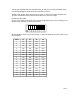
2) Notice there are four identical sections labeled TUBE 1 through TUBE 4. Each tube has
it’s own fuse, tube failure indicator, test point and bias adjust control.
3) First step is to insert the red (positive) meter lead into the TUBE 1 test point hole.
4) With your flat blade screwdriver, turn the BIAS ADJUST control to obtain a correct
reading from the chart below. Write down the reading.
5) Repeat this procedure for the other three tubes each time matching the reading written
down from the first tube.
6) Now allow the amp to warm up for about 10 minutes and retweak so all of the tube
readings are within 2mV (2millivolts) or .002volts DC of each other.
RECOMMENDED BIAS SETTINGS
6L6/5881 25mV to 35mV
EL34/6CA7 32mV to 40mV
E34L 35mV to 42mV
6550 35mV to 45mV
6V6 (JJ ONLY !!!!!!!) 18mV to 22mV
Displays differ from one meter to the next. Some may indicate, for example, 30.0 for 30 millivolts.
Others may show .030 for 30 millivolts. Knowing how your meter works if of the utmost
importance.
You should always check the bias readings whenever you replace output tubes and readjust if
needed. Since we’ve made it so simple, there is no reason to not.
PAGE 5
Additional features of the “POWER TUBE BIAS SECTION”
Fast Blo fuses. One per output tube. In the event of a power tube failure, the corresponding fuse
will open protecting the amp from additional damage and effectively removing the failed tube from