
Owner's Manual
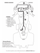
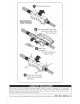
Table Of Contents

USING
THE
WIRING
KIT
POWER/GROUND CABLE (Wiring diagram
on
other
side)
1.
Remove seat to gain access to battery.
On
some models, a tray with the electronics control unit must also be removed.
(Consult factory service manual for steps that are specific to your year/model.)
2.
Make sure there
is
NO
fuse
in
the waterproof fuse holder. Remove if necessary.
3.
Unscrew the Positive(+) Battery terminal, connect the RED ring terminal end and re-connect the terminal.
4.
Unscrew the Negative(-) Battery terminal, connect the BLACK ring terminal end and re-connect the terminal.
5.
Locate the in-line fuse holder where it can be accessed later to install (or replace) fuse. Fuse holder should be
fastened using the built-in slots and supplied cable ties
6.
Lift or remove gas tank to route power/ground braided cables along with existing wiring. (Consult factory service
manual for steps that are specific to your year/model.) Use the supplied cable ties to fasten the braided
power/ground cable securely underneath the tank (either to existing loom
or
withing protective wire trough if
equipped).
7.
Continue to routing towards front area (stereo source unit) behind the fairing.
8.
Cut cables to appropriate length to reach amplifiers Power/Ground connections.
9.
Slip
the matching Red/Black PVC boots over the ends
of
the Power/Ground cables.
Strip 1
/2"
of
cable insulation
away and discard.
Insert
stripped copper cable inside the
8/1
OAWG
spade terminals and crimp securely.
Slide
the
protective PVC boots up over the exposed metal connectors.
REMOTE
WIRE (Wiring
diagram
on
other
side)
AFTERMARKET
STEREO:
1.
When
installing
with an Aftermarket radio, connect the 18GA Blue remote wire to Stereo's Blue/White Remote
output wire.
2.
Cut wire to length, strip back 1/4"
insulation and crimp the RED 18-22AWG
Spade
terminal to the amplifier
side
of
the wire.
3.
Secure
the wire with the supplied cable ties and connect to the
"REM"
remote input terminal at the amplifier.
NON
AFTERMARKET STEREO:
1.
When installing to an existing stereo without a Blue/White
"amp remote"
wire, remote power can
be
carefully
tapped behind the +12V cigarette lighter.
2.
Locate the switched power lead at the back
of
the the lighter socket
(typically
Orange/White). Use a
voiUohm
meter to verify the connection.
3.
Use the included 18-22AWG Butt connector to tap into the switched power lead.
4.
Follow
steps #2 and #3 above.
SPEAKER LEADS
(Wiring diagram
on
other
side)
TIP: EFX Speaker
cable
is
imprinted on 1
of
2
leads.
At
your
convnenience, chose the printed side
for
either
the(+)
or(-)
connections. Maintain consistency between the amp and speaker
for+/-
connections
or
speakers
will
be
out
of
phase.
1. Determine the length
of
each 16AWG speaker cable needed to reach between the amplifier Left and Right
speaker outputs to each speaker. (Cut excess wire length from ends which are not covered
in
protective braid.)
2.
Split
and strip back 1 /4"
insulation from the
Speaker
side
of
the cable. Crimp on the supplied Blue Female
14-16AWG
Speaker
terminals and connect to
the(+)
and(-)
terminals at the speaker.
3.
Split
and strip back
1/4"
insulation from the Amplifier side
of
the cable. Crimp
on
the supplied Blue
Spade
14-16AWG Speaker terminals and connect to
the(+)
and(-)
outputs at the amplifier.
4.
Repeat
Step
#3 for remaining speaker and use the supplied cable ties to secure cable away from suspension
or moving parts.
LIMITED
WARRANTY
Scosche
Industries, Inc.
warrants this product to be free from defects
in
material and workmanship for a period
of
1 Year from date
of purchase.
All
Scosche products are sold with the understanding that the purchaser has independently determined the suitability of
such products. This warranty does not cover any expenses incurred
in
the removal and reinstallation
of
the product. This warranty is
offered to the original purchaser of the product only.
This warranty does not apply to the product which has been damaged by accident, or which has been misued, altered,
or
installed
improperly. If
the product should prove defective within the warranty period, return the product with sales slip, postage prepaid to
Scosche
Industries, Inc.
Your dated sales slip/proof of purchase
will
establish your warranty eligibility. Scosche, at its option,
will
replace or repair the product free of charge and return the product to you postage paid .
In
no event
shall
Scosche be responsible for
claims
beyond the replacement value
of
the defective product or
in
any way
be
held liable or responsible for consequential or incidental
damages.
No
express warranties and no implied warranties, whether for fitness or any particular use, or otherwise, except as set forth above
(which is made expressly
in
lieu
of
all
other warranties)
shall
apply to products sold by Scosche. No waiver, alteration, addition, or
modification of the foregoing conditions
shall
be
valid
unless made
in
writing and signed by
an
executive officer of Scosche
Industries,
Inc.
No salesperson, representative, or agent
of
Scosche is authorized to give any guarantee, warranty,
or
make any representation contrary
to the above.
2