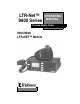
LTR-Net™ 9800 Series OPERATING MANUAL Trunked Mobile Radio 98x3/98x6 LTR-NET™ Mobile
LAND MOBILE PRODUCT WARRANTY - The manufacturer’s warranty statement for this product is available from your product supplier or from EFJohnson, 299 Johnson Avenue, Box 1249, Waseca, MN 56093-0514. Phone (507) 835-6222. Copyright© 1999 by the E.F. Johnson Company E.F. Johnson Company, which was founded in 1923, designs, manufactures, and markets radio communication products, systems, and services worldwide. E.F.
SAFETY INFORMATION SAFETY INFORMATION The FCC has adopted a safety standard for human exposure to RF energy. Proper operation of this radio under normal conditions results in user exposure to RF energy below the Occupational Safety and Health Act and Federal Communication Commission limits. WARNING DO NOT allow the antenna to touch or come in very close proximity with the eyes, face, or any exposed body parts while the radio is transmitting.
SAFETY INFORMATION FCC EXPOSURE LIMITS This mobile radio transceiver was tested by the manufacturer with an appropriate antenna in order to verify compliance with Maximum Permissible Exposure (MPE) limits set under Section 2.1091 of the FCC Rules and Regulations. The guidelines used in the evaluation are derived from Figure 1 (B) titled “Limits For General Population/Uncontrolled Exposure” which is from FCC report OET bulletin #65.
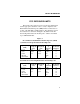
SAFETY INFORMATION Figure 2 lists the antenna whips and bases recommended for use in each frequency range. Each model of this radio was tested with the appropriate antenna listed. The antenna was mounted in the center of the roof of a domestic manufactured 4-door passenger sedan. The radio manufacturer has determined that the user and service personnel should remain one (1) meter in distance away from the antenna when transmitting.
TABLE OF CONTENTS TABLE OF CONTENTS SAFETY INFORMATION. . . . . . . . . . . . . . . . . . . . . . . . . . . . . . . . . . . . .4 QUICK REFERENCE GUIDE . . . . . . . . . . . . . . . . . . . . . . . . . . . . . . . . . 9 FEATURES . . . . . . . . . . . . . . . . . . . . . . . . . . . . . . . . . . . . . . . . . . . . . . . 10 General Features. . . . . . . . . . . . . . . . . . . . . . . . . . . . . . . . . . . . . . . . . . 10 LTR-Net Features. . . . . . . . . . . . . . . . . . . . . . . . . . . . . . . . . .
TABLE OF CONTENTS Placing Telephone Calls . . . . . . . . . . . . . . . . . . . . . . . . . . . . . . . . . . . . 29 Receiving a Telephone Call . . . . . . . . . . . . . . . . . . . . . . . . . . . . . . . . . 30 Landside-Originate Telephone Calls . . . . . . . . . . . . . . . . . . . . . . . . . . 31 LTR-NET AUXILIARY CALLS . . . . . . . . . . . . . . . . . . . . . . . . . . . . . . . 31 General . . . . . . . . . . . . . . . . . . . . . . . . . . . . . . . . . . . . . . . . . . . . . . . . .
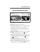
QUICK REFERENCE GUIDE QUICK REFERENCE GUIDE Red - Transmit Amber - Transmit (Reduced Pwr) Green - Busy Conv. Group (Channel) On-Off/Volume (Press/Rotate) Select Switch (Press/Rotate) System Scan List Horn Group Scan Monitor List Encrypt Phone/ Aux Call Scan Option Call Power On/Off - Press on-off /volume control. Set Volume Level - Rotate on-off/volume control. Change System or Group - Press Select switch to enable system or group select mode (indicated by ←/→ or __).
FEATURES FEATURES General Features • • • • • • • • • • • • • • • Up to approximately 99 systems with up to 99 groups each LTR-Net™, LTR®, and conventional operation Unique 8-character system and group identification tags System and group scan User programmable system and group scan lists Menu mode to control various functions Five programmable option switches Up to 16 banks selectable Proceed (clear-to-talk) tone Call indicator Horn alert Emergency quick select switch Companding (optional) Encryption (op
CONTROLS AND DISPLAY CONTROLS AND DISPLAY Transmit/Busy Indicator Microphone Jack Option Switches On-Off/Volume Speaker Select Switch Front Panel Controls On-Off Volume - Pressing this knob turns power on and off. The vehicle ignition switch may also control power as described in “Power Turn-Off Delay” on page 24. Rotating this knob sets the speaker volume (see page 15).
CONTROLS AND DISPLAY A/D - Scan list add/delete (see page 38) BANK - Bank select (see page 20) EMER - Emergency switch (see page 21) ENCPT - Encryption select (see page 21) FCN - Function select (see following description) HOME - Select home system/group (see page 22) (Menu) - Menu mode select (see page 33) AUX - Option select (see page 24) ROAM - Roam on-off (see page 43) SCAN - Scan on-off (see page 35) TEL - Selects telephone group (see “Tel Grp Select” on page 41) (Blank) - Not used (disabled) or one o
CONTROLS AND DISPLAY Antenna Jack Power Jack Speaker Jack Rear Panel Jacks and Connectors Antenna Jack - Miniature UHF jack for connecting the 50-ohm antenna. Power Jack - Connection point for the power cable which attaches to the vehicle battery. A nominal 12-volt DC, negative ground power source is required. Speaker Jack - Connection point for an optional external 4.7-ohm, 5-watt speaker. The internal speaker is automatically disabled when a speaker is plugged into this jack.
CONTROLS AND DISPLAY System Scan List Phone/ UID Grp 16-Character Encryption Message Area Scan Call Horn Alert Group Scan List Option Monitor Display Description 16-Character Message Area - Indicates the selected system and group (see page 16) and also error conditions and status information. - Indicates that the displayed system is in the scan list and scanned normally (see page 38). - Indicates that the displayed group is in the scan list and scanned normally (see page 38).
GENERAL OPERATION - Indicates that an option controlled by the AUX switch or OPTION menu parameter is enabled (see page 24). - Indicates that a call has been received on a group programmed for a call indicator (see page 21). To turn this indication off, press any key. - Indicates that the monitor mode is enabled. This mode disables Call Guard squelch and other squelch control features so that all messages are heard on conventional systems (see page 44).
GENERAL OPERATION Backlight Operation The display and keypad backlight can be controlled by the BACKLGT menu parameter (see page 33). The three states that can be selected are Bright, Dim, and Off. If this menu parameter is not selectable, the backlight is fixed in one of these states by programming. System/Group Display Modes The selected system and group are displayed using either a Numeric or Alpha display mode. The display mode is selectable if the S/G DISPL menu parameter is available (see page 33).
GENERAL OPERATION Selecting the System and Group The front panel Select switch is used to change the system and group. Pressing this switch toggles between the system and group select modes, and rotating it increases or decreases the system or group. In the Numeric display mode (see preceding description), the system select mode is indicated when the arrow points to “Sxx”, and the group select mode is indicated when it points to “Gxx” (see following illustration).
GENERAL OPERATION The current mode remains selected until the menu mode is selected or transceiver power is cycled. The programmed default mode is then selected if applicable. Setting Squelch Control NOTE: This sets the squelch level used for conventional calls. The squelch level for LTR-Net and LTR calls is preset and not affected by this adjustment. For more information on operating modes, refer to page 19.
GENERAL OPERATION ning (see page 35) or enable conventional channel monitoring (see page 44). LTR-Net, LTR, and Conventional Operation Introduction Each selectable system can be programmed for LTR-Net, LTR, or conventional operation. The type of operation that is programmed is determined by the radio equipment being used by your system operator. There are only a few differences in operation that are of concern to the user.
GENERAL FEATURES Conventional Operation In the conventional mode, selecting a system selects a specific radio channel, and selecting a group selects the special Call Guard squelch coding (if used) and other unique channel parameters such as call indicator operation. The Call Guard coding determines the mobile or group of mobiles being called and also the mobiles from which calls are received (see “Call Guard Squelch” on page 47).
GENERAL FEATURES Call Indicator The call indicator is “C” in the upper part of the display (see following illustration). The purpose of this indication is to show that a call was received while you were away from the vehicle. Individual groups can be programmed for this feature and it then turns on when a call is received on one of those groups. Call Indicator This indicator is turned off by pressing any button or cycling transceiver power.
GENERAL FEATURES parameter or option switch is not available, encryption may be fixed in the enabled mode by programming. When encryption is enabled, is indicated in the upper part of the display (see page 14). To transmit an encrypted call, encryption must be enabled as just described and the selected group must be programmed for encryption. Encrypted calls are always received regardless of the currently selected encryption mode and group programming (if the radio is equipped with encryption).
GENERAL FEATURES HOME option switch if it is programmed. The Home system/group is then displayed and it becomes the selected system/group. If no home system/group or FCN or HOME option switch has been programmed, this function is not available. A different home system/ group can be programmed for each bank. Horn Alert NOTE: The horn alert feature is not be available with some early models.
GENERAL FEATURES Auto Off/On Mode Ignition Switch - The horn alert always turns off when the ignition switch is turned on, and always turns on when the ignition switch is turned off (if there is a turn-off delay). Power Switch - The horn alert always reverts to the off condition when power is turned on by the power switch. NOTE: The preceding automatic operation overrides any mode that may have been selected by the HRN ALRT menu parameter.
GENERAL FEATURES Proceed (Clear-To-Talk) Tone This is a short tone that sounds shortly after the PTT switch is pressed to indicate that the radio system has been accessed and speaking can begin. The transceiver can be programmed so that this tone sounds on LTR-Net and LTR systems but not conventional systems. In addition, this and other tones can be disabled on all systems by the TONES menu parameter (see “Tone Select” on page 26) or system operator programming.
GENERAL FEATURES Stealth Mode The stealth mode disables the following tones and indicators so that they do not reveal that you are transmitting or otherwise indicate your presence. The speaker audio and display remain enabled in this mode. • • • All tones (see “Tone Select” on page 26) The front panel transmit/busy indicator (see page 11) Display backlight The stealth mode can be selected by the STEALTH menu parameter (see page 33), or is fixed in the on or off mode by programming.
STANDARD GROUP CALLS Silent - All tones are disabled. Keys - Only the Select switch and key press tones are enabled. Alerts - All tones except the preceding Key Beep tones are enabled. All - Both the Key Beep and Alert tones are enabled. Transmitter Thermal Foldback If the transmitter temperature increases to the point where damage to the transceiver could result, power is automatically cut back.
STANDARD GROUP CALLS 4. Press (and hold) the microphone PTT (push-to-talk) switch to talk and release it to listen. Operation with LTR-Net, LTR, and conventional calls is as follows: LTR-Net and LTR Operation • If the proceed tone is enabled (see page 25), it sounds shortly after the PTT switch is pressed if the radio system was successfully accessed. If it is not enabled, no tone sounds when the system is successfully accessed.
TELEPHONE CALLS not indicate that the radio system has been successfully accessed. 5. When the call is complete, place the microphone back on-hook. Receiving a Standard Group Call 1. Select or scan the system and group programmed for the call you want to receive (see page 35 for scan information). 2. When the message is received, the display usually changes to the system and group of the call. Take the microphone off-hook and press the PTT switch to talk and release it to listen.
TELEPHONE CALLS quickly select the telephone group in the current system, press the TEL option switch as described on page 41. When a group programmed for telephone calls is selected, is displayed. 2. To obtain the dial tone, briefly press the PTT switch. If the proceed tone is used (see page 25), press the PTT switch until this tone sounds. If a dial tone is then heard, proceed to step 4. Busy or no access conditions may also be indicated the same as described for standard group calls on page 28. 3.
LTR-NET AUXILIARY CALLS 2. When “ringing” is heard, press the PTT switch and respond. The PTT switch must be pressed to talk and released to listen the same as with standard calls. 3. When the call is finished, it should be terminated as in step 6 of the preceding section. Landside-Originate Telephone Calls If telephone calls can be placed, then it is usually possible to receive telephone calls from a landside telephone.
LTR-NET AUXILIARY CALLS Placing LTR-Net Auxiliary Calls 1. Select the LTR-Net system and group programmed for Auxiliary calls. When a group programmed for these calls is selected, is indicated in the upper part of the display. The group alpha tag displayed on the lower line may also indicate when one of these groups is selected. 2. To obtain a dial tone, briefly press the PTT switch. If the proceed tone is enabled, hold the PTT switch until this tone sounds.
OPTION SWITCHES AND MENU MODE selected. To receive a Directed Group call, the group of the call may need to be selected or scanned. A Unique ID call is indicated by a “ringing” tone similar to telephone calls, and a Directed Group call is indicated by the caller’s voice the same as with standard group calls. The transceiver may be programmed so that responses always occur on the last selected group.
OPTION SWITCHES AND MENU MODE table. Some parameters may not be displayed because they are not used or are in a fixed state or controlled by an option switch. Calls cannot be received or transmitted while the menu mode is selected.
SYSTEM AND GROUP SCANNING Using Menu Mode 1. To select the menu mode, press the Menu switch or FCN FCN (the FCN switch twice). The top line of the display indicates the function being edited, and the bottom line indicates the current status of that function (see following illustration). Function Status 2. To display the various functions that are controllable by the menu mode (top line indication), rotate the Select switch. The currently selected status of that function is displayed on the bottom line. 3.
SYSTEM AND GROUP SCANNING message is received. Shortly after the message is complete, scanning resumes (unless it has been disabled). Scanning is sequential through the programmed systems and groups. System and group scanning operate as follows: System Scanning - Detects calls on all systems that are in the system scan list. When system scanning is not used, calls are detected on only the currently selected system.
SYSTEM AND GROUP SCANNING Scan Types The type of scanning selected is determined by the menu mode SCN TYPE parameter (see page 33). If it is not selectable, the type of scanning is fixed by programming. The available scan types are as follows. SYSTEMS - Both system and group GROUPS - Group scanning only OFF - Both types disabled (SCAN switch non-functional) If the SCAN option switch is not programmed, the selected mode is always enabled.
SYSTEM AND GROUP SCANNING LTR and Conventional Mode Scanning When an LTR or conventional system is selected with system scanning enabled and roaming disabled, scanning is sequential through only the LTR and conventional systems in the scan list (LTR-Net systems are not scanned). If roaming is enabled, all three system types are scanned as described in the preceding LTR-Net description. Therefore, LTR and conventional systems are not scanned while on LTR-Net site.
SYSTEM AND GROUP SCANNING Saving Scan List If the menu mode SCN SAVE parameter is available, you can select if scan list changes are saved. If “On” is selected, changes are saved as they are made and the scan list is the same when power is turned on. Conversely, if “Off” is selected, they are not saved and the default scan list status of all systems and groups is reselected when power is turned on. If the menu SCN SAVE parameter is not selectable, the scan list save mode is fixed in one of these states.
LTR-NET AND LTR FEATURES Last Selected - Transmissions always occur on the system/group that was last selected by the Select switch. Therefore, the display may not indicate the system/group on which a response occurs. To respond to a call not on the selected system/group, first select the system/group of the call using one of the following methods: • Select it manually using the Select switch. • Before scanning resumes, exit the scan mode by pressing the SCAN switch.
LTR-NET AND LTR FEATURES again. However, you may want to wait a few seconds before making another attempt because a timer must time out before another attempt will be successful. A similar Transmit Disable On Busy feature is available on conventional systems (see page 46). Calls on Priority ID Codes With LTR-Net and LTR systems, each selectable group is programmed with a receive priority number.
LTR-NET FEATURES LTR-NET FEATURES NOTE: Other LTR-Net features are described starting on page 40. LTR-Net Standard and Special Calls The LTR-Net Special and Auxiliary calls are shown below. Refer to the descriptions which follow for more information. Telephone Unique ID Special Auxiliary Directed Group Standard Group Calls - Standard group calls are between two mobiles or between a mobile and a control station.
LTR-NET FEATURES Roaming LTR-Net radio localities (sites) can be linked together to provide wide area coverage. Then as you travel from locality to locality with roaming enabled, calls are automatically routed to your current location. Both standard group and special calls may be routed to other localities. To utilize the Roaming feature, proceed as follows: 1. An LTR-Net system must be selected. When an LTR or conventional system is selected, roaming is disabled. 2.
LTR FEATURES LTR FEATURES NOTE: Other LTR features are described starting on page 40. Standard Group Calls Standard group calls are between two mobiles or between a mobile and a control station. To place these calls in the LTR or LTRNet mode, simply select the desired group and press the PTT switch. The procedure for placing and receiving these calls is described starting on page 27.
CONVENTIONAL FEATURES Busy Indicator If the group is not automatically monitored as just described, it must be monitored manually. The simplest way to do this may be to note if a busy condition is indicated by the front panel multi-function indicator (see page 11). With scanning disabled and the squelch control properly adjusted (see page 18), note if this indicator is lighted green.
CONVENTIONAL FEATURES A conventional system must be selected to enable monitoring. If the microphone is taken off-hook with an LTR-Net or LTR system selected, scanning halts (unless off-hook detection is disabled) but monitoring is not selected. Transmit Disable On Busy The Transmit Disable On Busy feature automatically disables the transmitter if the selected group (channel) is busy and it has not been monitored when the PTT switch is pressed.
MISCELLANEOUS Talk-around is then automatically selected when one of these groups is selected. There is no special talk-around option switch or indicator. However, the group alpha tag on the lower line of the display may be used to indicate groups programmed for this feature. Talk-around is not available on LTR-Net and LTR systems. Call Guard Squelch The Call Guard squelch feature eliminates distracting messages intended for others using the channel.
MISCELLANEOUS Intercept Tone This is a siren-like tone (alternating high and low tones) which indicates the following no access and error conditions: • No Access - If this tone sounds shortly after pressing the PTT switch and “NO ACCES” is displayed, the radio system could not be accessed, perhaps because of an out-of-range condition (see “Operation At Extended Range” on page 54). Once this tone sounds, no more access attempts are made until the PTT switch is released and then pressed again.
MISCELLANEOUS Error Tone - This is a two-pitch tone that indicates that an error condition has occurred. LTR-Net Special Call Tones The following tones are generated by the LTR-Net equipment and are heard when making a telephone, unique ID, or directed group special call on an LTR-Net system. Confirmation Tone - This is a short tone that sounds when the number just dialed has been accepted by the system.
MISCELLANEOUS Conversation Time-Out Tone - Calls are limited to a certain length by the system. Thirty seconds before this time is reached, a “tick” begins sounding each second. When the 30-second time expires, the call is automatically terminated by the system. Turn-Around Tone - This is a single beep which may be used to indicate to the landside party when to respond to your transmission. It sounds when you release the PTT switch, and you may partially hear this tone.
MISCELLANEOUS power is turned on. This number indicates such things as frequency band, power output, and tier of the transceiver. The eighth digit is reserved and always “0”. NO ACCES - Indicates that the radio system could not be accessed, perhaps because of an out-of-range condition. Refer to “Operation At Extended Range” on page 54 for more information. NO PHONE - Indicates that there is no telephone group programmed in the current system when the Telephone option switch is pressed (see page 41).
MISCELLANEOUS TIMEOUT - Indicates that the transmitter has been disabled by the Time-Out Timer (see page 26). TX DISBL - Indicates that the transmitter has been disabled because the selected group is receive-only (see page 25). TX INHIB - Indicates that the transmitter has been disabled by the Transmit Inhibit feature (see page 40). Menu Mode Messages The following messages are displayed in the menu mode that is described starting on page 33.
MISCELLANEOUS SCN SAVE - Scan list save • ON = save, OFF = not saved SCN TYPE - Selects type of scanning • SYSTEM - Both system and group • GROUPS - Group scanning only • OFF - All scanning disabled S/G DISPL - System/group display mode • ALPHA • NUMERIC STEALTH - Stealth mode select • ON or OFF TONES - Beep tones select • SILENT - All tones disabled • KEYS - Only Select switch and key press tones sound • ALERTS - All tones sound except preceding Key Beeps sound • ALL - All the preceding tones sound System
MISCELLANEOUS speak and released as soon as the message is complete. If the proceed tone is used, wait for that tone to sound before speaking (see description on page 25). Operation At Extended Range When approaching the limits of radio range, the other party may not be able to hear your transmissions and there may be an increase in background noise when messages are received. You may still be out of range even though you can hear a message.
MISCELLANEOUS Transceiver Service If your transceiver is not operating properly, “OUT-LOCK”, “PROG ERR”, “SLEEPING”, or “CALL SVC” may be displayed. It may be possible to clear either of the first two conditions by turning off and then on again to reset the control logic. Also make sure that the controls are properly set and that the power, external speaker (if used), and accessory (if used), cables are securely plugged into the back of the transceiver.
MISCELLANEOUS 56 Part No. 002-9803-601 11-99hph Printed in U.S.A.