
Technical information

AUTOTRONIC CONTROLS CORPORATION • 1490 HENRY BRENNAN, EL PASO, TEXAS 79936 • (915) 857-5200 • FAX (915) 857-3344
www.msdignition.com email: msdtech@msdignition.com
98
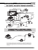
TIMING COMPUTER, PN 8980
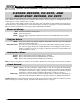
The MSD Timing Computer has a built-in timing curve designed for engines with locked-out timing. It is an
electronic version of a centrifugal advance. When the engine is cranking the timing retards 20° from the mechanical
locked out timing and remains there until 1,000 rpm. At this point, the timing begins to ramp back up and reaches
your mechanical setting by 3,000 rpm. This curve is not adjustable. This Control also has a single stage of retard that
is adjustable with plug-in modules. For 4 or 6-cylinder engines, see page 91 to program the control.
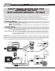
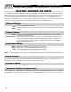
Red:
Black:
Yellow:
Connects to switched 12 volt source.
Connects to ground.
This is the trigger output to the Ignition. It will connect to the MSD’s White wire or Points
terminal.
White:
Violet and Green:
Connects to points or an ignition amplifier output. When this wire is used the Magnetic
Pickup is not (Violet and Green).
These wires are routed together in one harness and form the magnetic pickup connector.
This connector plugs directly into an MSD Distributor or Crank Trigger. The Violet wire is
positive (+) and the Green wire is negative (-). When this connector is used, the White wire
is not and should be sealed.
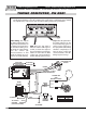
General Wiring
Trigger Wires
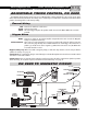
Retard Stage
There is a Gray and Black wire routed together into a 2-pin connector. The Gray is the activation wire for the retard
stage. The black is a ground wire.
When this wire is removed from ground, the retard stage is activated.
This is a ground wire. By connecting this to the Gray wire, the retard will not activate. A
mating connector is supplied to jump the two toghether
Gray:
Black:
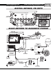
T
A
C
H
T
A
C
H
C+
C-
IGN
PTS
M+
M-
HEAVY RED
TO GROUND
NOT USED
WHITE
WHITE
TIMING
CONTROL
PN 8980
SWITCHED 12 VOLTS
FROM IGNITION KEY
YELLOW
RED
RED
BLACK
NOT
USED
ORANGE
HEAVY BLACK
PRO POWER COIL
PN 8201
+
GRAY
OR
GREEN
VIOLET
12V
ACTIVATION
STAGE 1
NITROUS
SOLENOID
+
TO BATTERY
TO BATTERY
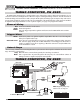
CYLINDERS
8
6
4
CUT LOOPS
NONE
RED
RED
&
BLUE
Note: Magnetic pickup loop
must be cut. See Page 91.
TIMING COMPUTER, PN 8980