
Technical information

AUTOTRONIC CONTROLS CORPORATION • 1490 HENRY BRENNAN, EL PASO, TEXAS 79936 • (915) 857-5200 • FAX (915) 857-3344
www.msdignition.com email: msdtech@msdignition.com
96
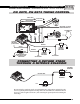
DIGITAL RETARD PN 8975
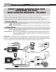
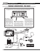
Red:
Black:
Yellow:
Connects to switched 12 volt source.
Connects to ground.
This is the trigger output to the Ignition. It will connect to the MSD’s White wire or Points
terminal.
White:
Violet and Green:
Connects to points or an ignition amplifier output. When this wire is used the Magnetic
Pickup is not (Violet and Green).
These wires are routed together in one harness and form the magnetic pickup connector.
This connector plugs directly into an MSD Distributor or Crank Trigger. The Violet wire is
positive (+) and the Green wire is negative (-). When this connector is used, the White
wire is not and should be sealed.
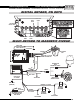
General Wiring
Trigger Wires
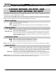
The Digital Retard Control, PN 8975, provides up to four different retard rates that can be activated at different
times. The four stages are cumulative up to 20° (6° on first stage, 4° second, 3° third, 2° fourth produces 15° total).
Instead of using rpm modules, this unit has four rotary dials that range from 0° - 9° in one degree increments.
Each stage is activated when the corresponding wire is removed from ground. If a stage is not going to be used,
its activation wire MUST be connected to ground, or positioned at zero on its dial.
Any time a setting is changed with a rotary dial, the ignition must be turned Off/On to reset.
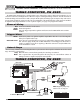
Activates the start retard when supplied to 12 volts. Once the engine reaches over 800 rpm, the retard will be
deactivated and will not return again until the ignition is turned Off or engine rpm drops below 500 rpm. There is a
rotary dial that controls the amount of retard in 5° increments with a max of 20°.
Cylinder Select
A rotary dial is used to select the number of cylinders. See page 97.
Magnetic Pickup Compensation
This circuit provides a timing compensation circuit for different style pickups. This adjustment is more important
for crank triggers and locked-out timing systems. If you are using the White wire for a trigger input, no adjustment
is necessary.
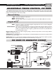
Activation Wires
When removed from ground, the FIRST stage is activated.
When removed from ground, the SECOND stage is activated.
When removed from ground, the THIRD stage is activated.
When removed from ground, the FOURTH stage is activated.
Brown:
Orange:
Gray:
Dark Blue:
Note: If a stage is not going to be used, the wire should be grounded or the rotary switch must be turned to Zero.
Start Retard