
Technical information

AUTOTRONIC CONTROLS CORPORATION • 1490 HENRY BRENNAN, EL PASO, TEXAS 79936 • (915) 857-5200 • FAX (915) 857-3344
www.msdignition.com email: msdtech@msdignition.com
91
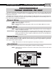
TIMING CONTROLS FOR MSD IGNITIONS
MSD offers a variety of Timing Controls that must be used with an MSD Ignition. Each Control has different
functions and options but they share common wiring. The Controls wire before the Ignition and always connect to
the MSD through the Ignition’s White wire, or Points terminal.
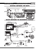
Just like an MSD Ignition, the Timing Controls have two inputs; a White wire for points or amplifiers or a 2-pin
magnetic pickup for MSD Distributors or Crank Triggers.
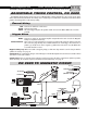
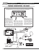
General Wiring
Trigger Wires
Activation Wires
Depending on which Timing Control you have, there will be a variety of colors and functions. The following pages
explain the operation of each Control and their wiring functions.
NOTE: It is recommended to check your ignition timing after installing any Timing Control. In some cases the timing
may be altered due to magnetic pickup compensation circuits.
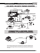
Red:
Black:
Yellow:
White:
Violet and Green:
Connects to points or an ignition amplifier output. When this wire is used the Magnetic
Pickup is not (Violet and Green).
These wires are routed together in one harness and form the magnetic pickup connector.
This connector plugs directly into an MSD Distributor or Crank Trigger. The Violet wire is
positive (+) and the Green wire is negative (-). When this connector is used, the White wire
is not and should be sealed.
WARNING: During installation, disconnect the battery. When disconnecting the battery always remove
the negative cable first and install it last.
Connects to switched 12 volt source.
Connects to ground.
This is the trigger output to the Ignition. It will connect to the MSD’s White wire or Points
terminal.
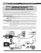
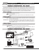
VIOLET LOOP
(START RETARD)
OR
WHITE LOOP
(MAGNETIC PICKUP)
RED LOOP
BLUE LOOP
*AVAILABLE ON CERTAIN
CONTROLS ONLY
HIGH SPEED
RETARD MODULE
RETARD
10
25
CUT LOOP
NONE
VIOLET
CYLINDERS
8
6
4
CUT LOOPS
NONE
RED
RED
&
BLUE
MAGNETIC PICKUP LOOP (WHITE)
MSD DIST., CRANK TRIGGER
POINTS/AMPLIFIER DIST.
*AVAILABLE ON CERTAIN CONTROLS ONLY
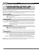
CUT LOOP
DO NOT CUT
Programming Loops