
Technical information

AUTOTRONIC CONTROLS CORPORATION • 1490 HENRY BRENNAN, EL PASO, TEXAS 79936 • (915) 857-5200 • FAX (915) 857-3344
www.msdignition.com email: msdtech@msdignition.com
67
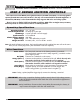
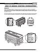
INSTALLING AN MSD DIS-2/DIS-4
IGNITION CONTROL
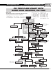
This section covers the MSD DIS-2 and DIS-4 line of Ignition Controls. The DIS-2 Ignitions can be
used on 4-cylinder engines equipped with two dual output coils. The DIS-4 Ignitions can be used
on 4, 6 or 8-cylinder engines equipped with up to four dual output coils. They will accept trigger
inputs from electronic DIS type ignition systems.
The DIS-HO Ignitions are designed for race only applications.
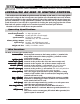
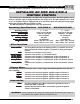
Operating Specifications DIS-2/DIS-4 DIS-2HO/DIS-4HO
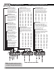
Wire F
unctions
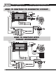
Trigger Wires
There are two or more circuits that can be used to trigger the MSD DIS Ignitions from the elec-
tronic amplifier.
Accessories
Operating Voltage:
Current Requirements:Current Requirements:
Current Requirements:Current Requirements:
Current Requirements:
RR
RR
R
PP
PP
P
M Output:M Output:
M Output:M Output:
M Output:
Spark Series Duration:Spark Series Duration:
Spark Series Duration:Spark Series Duration:
Spark Series Duration:
PrimarPrimar
PrimarPrimar
Primar
y Vy V
y Vy V
y V
oltage:oltage:
oltage:oltage:
oltage:
Energy Output Max:Energy Output Max:
Energy Output Max:Energy Output Max:
Energy Output Max:
WW
WW
W
eight and Size:eight and Size:
eight and Size:eight and Size:
eight and Size:
12 - 18 Volts
4.0A/ 7.4A at 10K rpm
14,000 w/ 14.4 Volts
20° Crankshaft
470 Volts
115 millijoules
DIS-2 3.7lbs, 8.5”x 4.5”x2.2”
DIS-4 4.5lbs, 9.5”x 4.5”x2.2”
12 - 18 Volts
5.3A/10A at 10K rpm
14,000 w/ 14.4 Volts
20° Crankshaft
470 Volts
170 millijoules
DIS-2 3.7lbs, 8.5”x 4.5”x2.2”
DIS-4 4.5lbs, 9.5”x 4.5”x2.2”
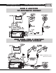
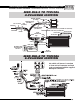
The heavy Red connects to the battery positive (+) terminal. The heavy
Black connects the battery negative (-) terminal or other good engine
ground.
Connects to a switched 12 volts source.
Connects to the positive (+) coil terminal/wire.
Connects to the negative (-) terminal/wire of the coil (Channel 1).
Connects to the negative (-) terminal/wire of the coil (Channel 2).
Connects to the negative (-) terminal/wire of the coil (Channel 3, DIS-4
only).
Connects to the negative (-) terminal/wire of the coil (Channel 4, DIS-4
only).
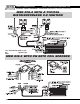
Connects to the electronic ignition amplifier output of channel 1.
Connects to the electronic ignition amplifier output of channel 2.
Connects to the electronic ignition amplifier output of channel 3.
Connects to the electronic ignition amplifier output of channel 4.
Two Step Activation wire. When connected to ground, the lower or
launch rpm limit is activated.
Ignition interrupt feature. When connected to ground the ignition
output is interrupted.
PP
PP
P
oo
oo
o
wer Cables:wer Cables:
wer Cables:wer Cables:
wer Cables:
Red:Red:
Red:Red:
Red:
BroBro
BroBro
Bro
wn/Orange:wn/Orange:
wn/Orange:wn/Orange:
wn/Orange:
BroBro
BroBro
Bro
wn/Wwn/W
wn/Wwn/W
wn/W
hite:hite:
hite:hite:
hite:
BroBro
BroBro
Bro
wn/Green:wn/Green:
wn/Green:wn/Green:
wn/Green:
BroBro
BroBro
Bro
wn/Ywn/Y
wn/Ywn/Y
wn/Y
elloello
elloello
ello
w:w:
w:w:
w:
BroBro
BroBro
Bro
wn/Vwn/V
wn/Vwn/V
wn/V
iolet:iolet:
iolet:iolet:
iolet:
WW
WW
W
hite:hite:
hite:hite:
hite:
Green:Green:
Green:Green:
Green:
YY
YY
Y
elloello
elloello
ello
w:w:
w:w:
w:
VV
VV
V
iolet:iolet:
iolet:iolet:
iolet:
Blue:Blue:
Blue:Blue:
Blue:
BroBro
BroBro
Bro
wn:wn:
wn:wn:
wn:
WARNING: During installation, disconnect the battery. When disconnecting the battery al-
ways remove the negative cable first and install it last.