
Technical information

AUTOTRONIC CONTROLS CORPORATION • 1490 HENRY BRENNAN, EL PASO, TEXAS 79936 • (915) 857-5200 • FAX (915) 857-3344
www.msdignition.com email: msdtech@msdignition.com
47
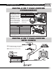
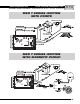
INSTALLING AN MSD 7AL-2 AND 7AL-3
IGNITION CONTROL
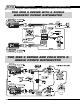
This section covers the MSD 7AL-2 and 7AL-3 Ignition Controls. These ignitions share the same wiring
to run the vehicle, but the 7AL-3 has several optional accessories that can be connected. The 7AL-2 has
a single stage rev limiter while the 7AL-3 has a Three Step Rev Control along with other accessories
which are explained on the next page.
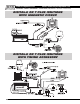
Both ignitions will install to most vehicles with a 12 volt electrical system and a distributor
that is triggered with points, electronic amplifiers or magnetic pickups.
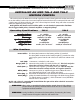
Operating Specifications 7AL-2 7AL-3
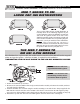
Wire Functions
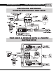
Power Cables: The heavy Red connects to the battery positive (+) terminal.
The heavy Black connects to the battery negative (-) terminal or other
good engine ground. On the 7AL-3 these are called out as Batt+ and
Batt -.
Red (IGN): Connects to a switched 12 volt source.
Orange (COIL +): Connects to the positive (+) terminal of the coil. This is the only wire
that makes electrical contact with the coil (+) terminal.
Black (COIL -): Connects to the negative (-) terminal of the coil. This the only wire
that makes electrical contact with the coil negative terminal.
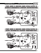
White (PNTS): Connects to a points or amplifier trigger source. When this wire is
used, the Magnetic Pickup is not (Green and Violet).
Violet (Mag +): These wires are routed into a 2-pin connector. It connects to the magnetic
Green (Mag-): pickup of an MSD Distributor or Crank Trigger. The Violet is mag positive
(+) and the Green is negative (-). If this connector is used, the White
wire will not be connected.
On the 7AL-2 there is a ground stud located below the rpm socket. Other electrical accessories
can be connected to this ground.
12 - 18 Volts
1 Amp per 1,000 rpm
14,000 w/ 14.4 Volts
20° Crankshaft
550 Volts
160 Millijoules
4.75lbs, 8”x 3.75”x5.75”
12 - 18 Volts
1 Amp per 1,000 rpm
14,000 w/ 14.4 Volts
20° Crankshaft
470 Volts
115 millijoules
4.75lbs, 8”x 3.75”x5.75”
Operating VOperating V
Operating VOperating V
Operating V
oltage:oltage:
oltage:oltage:
oltage:
Current Requirements:Current Requirements:
Current Requirements:Current Requirements:
Current Requirements:
RR
RR
R
PP
PP
P
M Range:M Range:
M Range:M Range:
M Range:
Spark Series Duration:Spark Series Duration:
Spark Series Duration:Spark Series Duration:
Spark Series Duration:
PrimarPrimar
PrimarPrimar
Primar
y Vy V
y Vy V
y V
oltage:oltage:
oltage:oltage:
oltage:
Energy Output Max:Energy Output Max:
Energy Output Max:Energy Output Max:
Energy Output Max:
WW
WW
W
eight and Size:eight and Size:
eight and Size:eight and Size:
eight and Size:
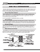
WARNING:
WARNING:
When using a capacitive discharge ignition control, there is high voltage
present at the coil primary terminals. Never touch the coil or connect test
equipment to these terminals.
During installation, disconnect the battery. When disconnecting the battery
always remove the negative cable first and install it last.