
Technical information

AUTOTRONIC CONTROLS CORPORATION • 1490 HENRY BRENNAN, EL PASO, TEXAS 79936 • (915) 857-5200 • FAX (915) 857-3344
www.msdignition.com email: msdtech@msdignition.com
40
INSTALLING MSD 6TN, 6ALN AND 6HVC
DUAL RACE IGNITIONS
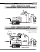
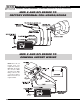
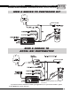
This section covers how to wire redundant ignition systems featuring the MSD 6TN, 6ALN, GM
Heavy Duty Ignition and the 6 HVC Professional Ignition. These ignitions are designed primarily for
circle track and road course racing where running a redundant ignition system is commonplace.
These Ignition Controls feature NASCAR approved Weathertight connectors, a clear baseplate for
easy tech inspection and a clear silicone potting for added vibration protection.
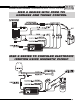
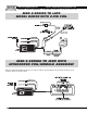
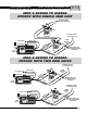
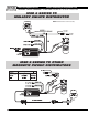
There are many different options when running a redundant ignition. MSD also offers several
components such as Dual Pickup Distributors and an Automatic Coil Selector for these systems.
NOTE: The 6-HVC Ignition must be used with the HVC Coil, PN 8250.
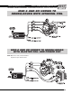
Wire Functions
Power Cables: The heavy red connects to the battery positive (+) terminal. The heavy
Black connects to the battery negative (-) terminal or other good
engine ground.
Red: Connects to a switched 12 volts source.
Orange: Connects to the positive (+) terminal of the coil. This is the only wire
that makes electrical contact with the coil positive terminal.
Black: Connects to the negative (-) terminal of the coil. This the only wire
that makes electrical contact with the coil negative terminal.
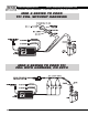
White: This is one of the wires that provides a trigger signal for the MSD. It
connects to the breaker points, electronic ignition amplifier output or
to the Yellow wire of an MSD timing accessory. When this wire is
used, the Magnetic pickup wires are not (Violet and Green wires).
Violet and Green: These wires are routed together in one harness to form the magnetic
pickup connector. They plug directly into an MSD Distributor or Crank
Trigger. The Violet wire is positive (+) and the Green wire is negative
(-). When they are used, the White wire is not.
Operating VOperating V
Operating VOperating V
Operating V
oltage:oltage:
oltage:oltage:
oltage:
Current Requirements:Current Requirements:
Current Requirements:Current Requirements:
Current Requirements:
RR
RR
R
PP
PP
P
M Range:M Range:
M Range:M Range:
M Range:
Spark Series Duration:Spark Series Duration:
Spark Series Duration:Spark Series Duration:
Spark Series Duration:
PrimarPrimar
PrimarPrimar
Primar
y Vy V
y Vy V
y V
oltage:oltage:
oltage:oltage:
oltage:
Energy Output MaxEnergy Output Max
Energy Output MaxEnergy Output Max
Energy Output Max
es:es:
es:es:
es:
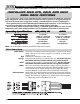
10-18 Volts
.7 Amps per 1,000 rpm
15,000 w/ 14.4 Volts
20° Crankshaft
550 Volts
150 Millijoules
10-18 Volts
1 Amp per 1,000 rpm
15,000 w/ 14.4 Volts
20° Crankshaft
460-480 Volts
105-115 Millijoules
Operating Specifications Operating Specifications
Operating Specifications Operating Specifications
Operating Specifications
6TN, 6ALN, GM 6TN, 6ALN, GM
6TN, 6ALN, GM 6TN, 6ALN, GM
6TN, 6ALN, GM
6 HVC 6 HVC
6 HVC 6 HVC
6 HVC