
Technical information

AUTOTRONIC CONTROLS CORPORATION • 1490 HENRY BRENNAN, EL PASO, TEXAS 79936 • (915) 857-5200 • FAX (915) 857-3344
www.msdignition.com email: msdtech@msdignition.com
18
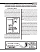
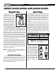
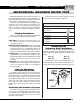
The MSD Flying Magnet Crank Trigger System is the
most accurate way possible to trigger the ignition. This
is due to fact that the trigger signal is coming directly
from the source of piston position in the cylinder; the
crankshaft.
Distributors are accurate, but the piston position is
derived through the timing chain, the camshaft, cam
gear and finally to the distributor shaft. There are no
mechanical variables in piston position when using a
crank trigger system.
Non-Magnetic Pickup
The MSD Crank Trigger System uses a non-magnetic
pickup to trigger the ignition. Magnets are embedded
in the flywheel to produce the trigger signal. The non-
magnetic pickup can only be triggered by the magnets
in the flywheel. This design prevents the chance of
false triggering.
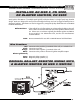
When installing the pickup, it is recommended to
twist the wires together and route the wires near the
frame or engine. These areas act as an electrical shield
against electrical
interference in
the air. Also
keep the wires
away from any
spark plug wires, coil wires and ignition wires.
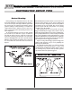
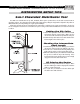
Pickup Mounting
The MSD Crank Trigger Kits come with all of the hard-
ware needed to mount the pickup. Many kits feature a
bracket that can be installed on either side of the
engine block. Some kits are also supplied with several
spacers to help obtain the correct alignment of the
pickup and wheel. Due to the variety of balancers and
pulleys, some modifying may be required to achieve
the correct positioning of the bracket and pickup.
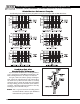
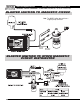
Trigger Wheel Mounting
Unlike conventional crank trigger systems using a
magnetic pickup, the MSD trigger wheel must be
mounted in the proper position. This is due to the
polarity of the magnets in the wheel. If the wheel is
reversed, the trigger signal will be affected and may
advance the timing and cause inconsistent triggering
accuracy. On the wheel there is an arrow which must
point in the same direction as the engine rotation. Make
sure this is installed correctly.
When the wheel and
trigger pickup bracket
are mounted, make
sure the pickup is
positioned in the
center of the trigger
wheel. If it is not, the
trigger signal can be
affected. If they are
not aligned, the
bracket may require
different spacers.
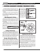
Setting the Air Gap
The air gap between the pickup and trigger wheel is
important, however it does not affect the performance
in regards to your ET or mph. It affects the strength of
the trigger signal. The farther away the pickup is from
the wheel the weaker the trigger signal becomes. This
could come into effect at cranking rpm.
The minimum air gap is 0.050" and any closer the
chance of the wheel hitting the pickup at high rpm
comes into play. Some big cubic inch engine builders
(600-800ci) recommend 0.060" - 0.080" air gap due to
the flexing of the crankshaft.
A good rule of thumb is to run the pickup all the way
in until contacts the trigger wheel. Then, back the pickup
out one full turn. This will set approximately 0.060"
airgap, but always check the gap with a set of feeler
gauges and in different areas of the wheel.
FLYING MAGNET CRANK TRIGGER TIPS