
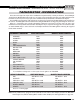
Technical information

AUTOTRONIC CONTROLS CORPORATION • 1490 HENRY BRENNAN, EL PASO, TEXAS 79936 • (915) 857-5200 • FAX (915) 857-3344
www.msdignition.com email: msdtech@msdignition.com
113
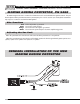
This 2-pin connector plugs into a Cam Sync Sensor to indicate when the number
one cylinder is triggered. The wires are Lt Blue and Lt Green.
White/Blue
Violet/Blue
Red/Green
RPM Controls
This connector plugs into the MSD Ignition Control's rpm module receptacle. Not
used with MSD DIS Ignitions.
Yellow 2-Pin
Plug
When grounded, this wire activates several features including; Launch Retard value
and will reset the Shift Light sequence to 1
st
gear. (On single channel ignitions it also
activates the Launch rpm limit.) Splice it into the DIS Ignition's blue wire.
This wire activates the Burnout rev limit when grounded, when used with single
channel ignitions only.
Dark Blue
Light Blue
Shift Light activation wire. Supplies ground to activate a light.
Orange/Yellow
Retard Stages
This wire activates the first retard stage when it is applied to 12 volts. When 12 volts
is removed the retard is deactivated.
Pink
Injector output #1 to Fuel Injector
Injector output #2 to Fuel Injector
(+) 12 Volts to Fuel Injectors.
Fuel Adder
Lt Blue and
Lt Green
Cam Sync
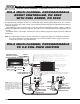
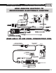
This wire connects to electronic ignition amplifier output or to the trigger output of the
ECU. When this wire is used, the Magnetic Pickup connector is not used.
This wire is responsible for turning the MSD On and Off. Connects to a switched 12
volt source such as the ignition key or switch.
This wire connects to a good ground, either at the battery negative (-) terminal or to
the engine.
Red
Black
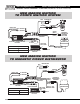
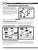
Trigger
Wires
There are two circuits that can be used to trigger the Controller; a Points/Amplifier
circuit (the White, Green, Yellow, Violet wire) and a Magnetic Pickup circuit (the Green
and Violet wires). The two circuits will never be used at the same time.
This wire connects to electronic ignition amplifier output or to the trigger output of the
ECU. When this wire is used, the Magnetic Pickup connector is not used.
This wire connects to electronic ignition amplifier output or to the trigger output of the
ECU. When this wire is used, the Magnetic Pickup connector is not used.
Green
(Channel 2)
Yellow
(Channel 3)
Violet & Green
(Magnetic
Pickup
Connector)
These wires are routed together in one harness as the magnetic pickup connector.
The connector plugs directly into an MSD distributor or crank trigger. It will also
connect to aftermarket pickups. The Violet wire is positive (+) and the Green wire is
negative (-). When these wires are used, the White, Green, Yellow, Violet wire
are not. (Distributor applications only.)
Brown/White
Channel 1 output trigger signal. It connects to the trigger input of the MSD Ignition
Control.
This wire connects to electronic ignition amplifier output or to the trigger output of the
ECU. When this wire is used, the Magnetic Pickup connector is not used.
Channel 2 output trigger signal. It connects to the trigger input of the MSD Ignition
Control.
Channel 3 output trigger signal. It connects to the trigger input of the MSD Ignition
Control.
Channel 4 output trigger signal. It connects to the trigger input of the MSD Ignition
Control.
Violet
(Channel 4)
Brown/Green
Brown/Yellow
Brown/Violet
This wire activates the second retard stage when it is applied to 12 volts. When 12
volts is removed the retard is deactivated.
Dark Brown
This wire activates the third retard stage when it is applied to 12 volts. When 12 volts
is removed the retard is deactivated.
Tan
White
(Channel 1)