
Technical information

AUTOTRONIC CONTROLS CORPORATION • 1490 HENRY BRENNAN, EL PASO, TEXAS 79936 • (915) 857-5200 • FAX (915) 857-3344
www.msdignition.com email: msdtech@msdignition.com
106
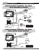
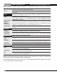
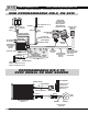
This wire is responsible for turning the MSD On and Off. Connects to a switched 12
volt source such as the ignition key or switch.
This wire connects to a good ground, either at the battery negative (-) terminal or to
the engine.
Red
Black
Trigger
Wires
There are two circuits that can be used to trigger the Controller; a Points circuit (the
White wire) and a Magnetic Pickup circuit (the Green and Violet wires). The two circuits
will never be used at the same time.
White
This wire is used to connect to breaker points, electronic ignition amplifier output or
to the trigger output of the ECU. When this wire is used, the Magnetic Pickup
connector is not used.
Violet & Green
(Magnetic
Pickup
Connector)
These wires are routed together in one harness as the magnetic pickup connector.
The connector plugs directly into an MSD distributor or crank trigger. It will also
connect to aftermarket pickups. The Violet wire is positive (+) and the Green wire is
negative (-). When these wires are used, the White wire is not.
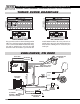
Brown/White
This is the output trigger signal. It connects to the points input of the MSD Ignition
Control.
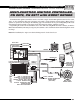
Cam Sync
Lt Blue and
Lt Green
This 2-pin connector plugs into a Cam Sync Sensor to indicate when the number
one cylinder is triggered. The wires are Lt Blue and Lt Green.
This is where the fiber optic cable of the PN 7555 Inductive Sync Kit connects to take
advantage of the Individual Cylinder Management feature. This must be covered
when using the 2-pin cam sync input.
RPM Controls
This connector plugs into the MSD Ignition Control's rpm module receptacle.Yellow 2-Pin
Plug
When 12 volts are applied, this wire activates several features including; Launch rev
limit, Launch Retard value and will reset the Shift Light sequence to 1
st
gear.
Dark Blue
This wire activates the Burnout rev limit when 12 volts are applied.
Light Blue
Shift Light activation wire. Supplies ground to activate a light.Orange/Yellow
This wire activates the first retard stage when it is applied to 12 volts. When 12 volts
is removed the retard is deactivated.
Pink
This wire activates the second retard stage when it is applied to 12 volts. When 12
volts is removed the retard is deactivated.
Dark Brown
This wire activates the third retard stage when it is applied to 12 volts. When 12 volts
is removed the retard is deactivated.
Ta n
LED - The LED will verify the trigger signals. It will also flash a trouble code 11 if there is a problem with
the Cam Sync signal (for individual cylinder management).
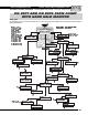
The Controllers share many of the same features as the Programmable Digital-7 Ignition. See page 56
for more information and wiring samples.
Fiber Optic
Connection
Retard Stages