
Technical information

AUTOTRONIC CONTROLS CORPORATION • 1490 HENRY BRENNAN, EL PASO, TEXAS 79936 • (915) 857-5200 • FAX (915) 857-3344
www.msdignition.com email: msdtech@msdignition.com
103
VARI-CURVE CONTROL, PN 8983
The MSD Vari-Curve allows you to set an ignition curve for advance or to retard throughout the rpm range. The
starting and ending rpm points of the curve are selected with rpm modules. The range of timing change is set with
degree modules and installed in either a negative (retard) or positive (advance) module position.
There are also two retard stages that are adjustable with plug-in modules. These retard steps will be activated
when their corresponding control wires are removed from ground. There is also an optional start retard that can be
set to retard the timing either 10° or 25° while the engine cranks.
The PN 8983 must be used with an MSD Ignition Control and can be used on 4, 6 or 8-cylinder engines.
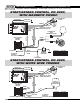
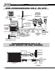
Start Retard
Retard Stage
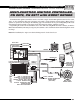
Red:
Black:
Yellow:
Connects to switched 12 volt source.
Connects to ground.
This is the trigger output to the Ignition. It will connect to the MSD’s White wire or Points
terminal.
White:
Violet and Green:
Connects to points or an ignition amplifier output. When this wire is used the Magnetic
Pickup is not (Violet and Green).
These wires are routed together in one harness and form the magnetic pickup connector.
This connector plugs directly into an MSD Distributor or Crank Trigger. The Violet wire is
positive (+) and the Green wire is negative (-). When this connector is used, the White wire
is not and should be sealed.
General Wiring
Trigger Wires
Violet:
Violet Loop:
Activates the start retard when supplied to 12 volts. Once the engine reaches over 1,300
rpm, the retard will be deactivated and will not return again until the ignition is turned Off
or engine rpm drops below 400 rpm.
Under the cover next to the Blue and Red cylinder loops is a Violet loop. This adjusts the
start retard. When is not cut, the retard is 10°, cutting it will retard it 25°.
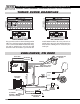
There are two retard stages that can activated independently. If used at the same time, the retard rates are
cumulative. When the retard is not being used, the activation wire(s) MUST be grounded or a Zero degree module
must be installed. If not, the timing will be retarded the default amount, 20°.
Brown/Orange:
Brown/White:
When this wire is removed from ground, the #1 retard stage is activated.
When this wire is removed from ground, the #2 retard stage is activated.
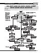
Cylinder Select: There are two wire loops under the small cover on the side of the control. For 6-cylinder operation,
cut the Red loop, for 4-cylinder engines, cut both the Red and Blue loop. See page 91.