
Specifications


6 Installation Instructions Efficient Networks, Inc.
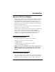
3 After attaching the ferrite choke, attach the USB cable to the USB
port on the back of the modem and connect the other end of the cable
to the USB port on your computer.
4 Connect one end of the USB cable (marked with this symbol: )
to the
USB port on the back of the modem and connect the other end
of the cable to the USB port on your computer.
5 Connect one end of an RJ11 telephone cable to the modem’s DSL port
and the other end to the DSL service port (wall jack).
6 Proceed with the software installation desribed in the next section.
Table 1 Modem LED Indicator Descriptions
LED Description
Off No line power or no USB power
Yellow Powering up, firmware being download
Blinking Yellow/Green Has passed Power-on Self Test (POST), looking
for tone on ADSL line
Blinking Green Has passed Power-on Self Test (POST), ADSL
line is attempting to train
Green Unit is functional, ADSL line is connected and
ATM cell delineation is present
Red Hardware failure detected
Blinking Yellow Modem in maintenance state (occurs with new
firmware download or factory testing)
USB Cable
Your Computer
wall jack
Modem
RJ11
Cable
Plug cable
into DSL
Power