
- Siemens Cordless Telephone User Manual

Servo control
3.12 Motor data identification
Drive Functions
Function Manual, (FH1), 07/2007 Edition, 6SL3097-2AB00-0BP4
97
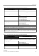
Table 3-14 Data determined using p1960 for synchronous motors (rotating measurement)
Determined data Data that are accepted (p1960 = 1)
r1934 q inductance identified -
r1935 q inductance identification current -
Note:
The q inductance characteristic can be used as basis to manually determine the data for the current controller adaptation
(p0391, p0392 and p0393).
r1937 torque constant identified p0316 motor torque constant
r1938 voltage constant identified p0317 motor voltage constant
r1939 reluctance torque constant identified p0328 motor reluctance torque constant
r1947 optimum load angle identified p0327 optimum motor load angle
r1969 moment of inertia identified p0341 motor moment of inertia
* p0342 ratio between the total moment of inertia and that of
the motor
+ p1498 load moment of inertia
r1973 encoder pulse number identified -
Note:
The encoder pulse number is only determined with a very high degree of inaccuracy (p0407/p0408) and is only suitable for
making rough checks. The sign is negative if inversion is required (p0410.0).
r1984 Pole position identification angular difference p0431 Angular commutation offset
Note:
r1984 indicates the difference of the angular commutation offset before being transferred into p0431.
For linear motors (p0300 = 4xx), p1959 is pre-set so that only the q inductance, the angular
commutation offset and the high inertia mass are measured (p1959.05 = 1 and p1959.10 =
1), as generally the travel limits do not permit longer traversing distances in one direction.
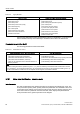
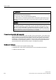
&DEOH
0RWRU
5
&
&DEOH
&DEOH
S S
S>0@
S>0@
S>0@ S>0@ S>0@
S>0@
0RWRU0RGXOH
/
˰6 ˰5 5
0
/
/
55
6
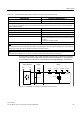
Figure 3-18 Equivalent circuit diagram for induction motor and cable