
- Siemens Cordless Telephone User Manual

Servo control
3.9 V/f control for diagnostics
Drive Functions
Function Manual, (FH1), 07/2007 Edition, 6SL3097-2AB00-0BP4
85
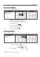
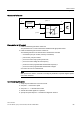
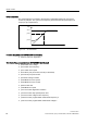
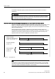
Structure of V/f control
5DPSIXQFWLRQ
JHQHUDWRU
S
S S
S
S
Q
I
8
S
Figure 3-14 Structure of V/f control
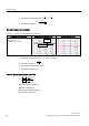
Prerequisites for V/f control
1. Initial commissioning has been carried out:
The parameters for V/f control have been initialized with appropriate values.
2. Initial commissioning has not been carried out:
The following relevant motor data must be checked and corrected:
– r0313 Motor pole pair number, actual (or calculated)
– p0314 motor pole pair number
– p1318 V/f control ramp-up/ramp-down time
– p1319 V/f control voltage at zero frequency
– p1326 V/f control programmable characteristic frequency 4
– p1327 V/f control programmable characteristic voltage 4
V/f control can now be commissioned.
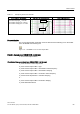
Note
With synchronous motors, V/f mode is normally only stable at low speeds. Higher speeds
can induce vibrations.
Commissioning V/f control
1. Verify the preconditions for V/f control mode.
2. Set p0311 –> rated motor speed
3. Set p1317 = 1 –> activates the function
4. Activate the enable signals for operation
5. Specify the speed setpoint –> evaluate the diagnostic function