
- Siemens Cordless Telephone User Manual

Servo control
3.7 Current setpoint filter
Drive Functions
Function Manual, (FH1), 07/2007 Edition, 6SL3097-2AB00-0BP4
81
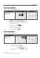
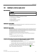
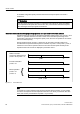
Band-stop with defined notch depth
Table 3-4 Example of band-stop with defined notch depth
STARTER filter parameters Amplitude log frequency curve Phase frequency curve
Blocking frequency f
Sp
= 500 Hz
Bandwidth f
BB
= 500 Hz
Notch depth K = -20 dB
Reduction Abs = 0 dB
. G%
Simplified conversion to parameters for general order filters:
No reduction or increase after the blocking frequency
Defined notch at the blocking frequency K[dB] (e.g. -20 dB)
● Numerator frequency f
Z
= f
Sp
● Numerator damping
.
6S
%%
=
I
I
'
● Denominator natural frequency f
N
= f
Sp
● Denominator damping
6S
%%
1
I
I
'
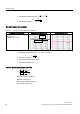
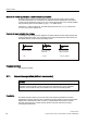
Band-stop with defined reduction
Table 3-5 Example of band-stop
STARTER filter parameters Amplitude log frequency curve Phase frequency curve
Blocking frequency f
SP
= 500 Hz
Bandwidth f
BB
= 500 Hz
Notch depth K = -∞ dB
Reduction ABS = -10 dB
$EVG%
General conversion to parameters for general order filters:
● Numerator natural frequency
6S
=
=
II
2
=
π
ω
=
● Numerator damping
$EV
6S
%%
$EV
.
=
I
I
'
10
2
2
2
20
20
1010
1
1
2
1
10
•
+
⎟
⎟
⎟
⎟
⎠
⎞
⎜
⎜
⎜
⎜
⎝
⎛
−••=