
- Siemens Cordless Telephone User Manual


Basic information about the drive system
12.10 Rules for wiring with DRIVE-CLiQ
Drive Functions
514 Function Manual, (FH1), 07/2007 Edition, 6SL3097-2AB00-0BP4
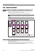
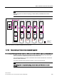
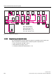
12.10.3 Sample wiring for vector drives
Drive line-up comprising three Motor Modules (chassis) with identical pulse frequencies or vector
(booksize)
Motor Modules (chassis) with identical pulse frequencies or vector (booksize) can be
connected to a DRIVE-CLiQ interface on the Control Unit.
In the following diagram, three Motor Modules are connected to interface X101.
Note
This topology does not match the topology created offline by STARTER and must be
changed.
'ULYH'ULYH'ULYH
60&
960
60&
60&
HQFRGHU
3RZHUUDWLQJ
&8
000
,QIHHG
;
;
;
;
;
;
;
;
;
;
;
;
;
;
;
;
$FWLYH
/LQH
0RGXOH
6LQJOH
0RWRU
0RGXOH
6LQJOH
0RWRU
0RGXOH
6LQJOH
0RWRU
0RGXOH
;
$FWLYH
,QWHUIDFH
0RGXOH
;
;
;
;
;
;
'5,9(&/L4
Figure 12-25 Drive line-up (chassis) with identical pulse frequencies
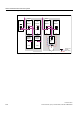
Drive line-up comprising four Motor Modules (chassis) with different pulse frequencies
Motor Modules with different pulse frequencies must be connected to different DRIVE-CLiQ
interfaces on the Control Unit.
In the following diagram, two Motor Modules (400 V, output ≤ 250 kW, pulse frequency
2 kHz) are connected to interface X101 and two Motor Modules (400 V, output > 250 kW,
pulse frequency 1.25 kHz) are connected to interface X102.