
- Siemens Cordless Telephone User Manual

Basic information about the drive system
12.10 Rules for wiring with DRIVE-CLiQ
Drive Functions
Function Manual, (FH1), 07/2007 Edition, 6SL3097-2AB00-0BP4
509
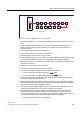
Note
If an additional encoder is connected to a Motor Module, it is assigned to this drive as
encoder 2 in the automatic configuration.
960
&8
;
;
;
;
$FWLYH
/LQH
0RGXOH
;; ;;
;; ;;
;; ;;
;
6LQJOH
0RWRU
0RGXOH
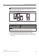
Figure 12-24 Example of a topology with VSM for Booksize and Chassis components
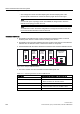
Table 12-15 VSM connection
Component VSM connection
Active Line Module Booksize X202
Active Line Module (chassis) X402
Power Modules The VSM is not supported.
Important!
All of the nodes on the DRIVE-CLiQ line must have the same sampling time in p0115[0]. otherwise
the VSM must be connected to a separate DRIVE-CLiQ interface on the Control Unit.
● Only one final node should ever be connected to free DRIVE-CLiQ ports of components
within a DRIVE-CLiQ line (e.g. Motor Modules wired in series), e.g. one Sensor
Module or one Terminal Module without forwarding to additional components.
● If possible, Terminal Modules and Sensor Modules of direct measuring systems should
not be connected to the DQ line of Motor Modules but rather to free DRIVE-CLiQ ports of
the Control Unit.