
- Siemens Cordless Telephone User Manual

Basic information about the drive system
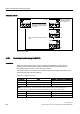
12.7 Examples of replacing components
Drive Functions
500 Function Manual, (FH1), 07/2007 Edition, 6SL3097-2AB00-0BP4
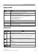
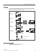
Action Reaction Comments
• Load the project from the
Control Unit to the
STARTER (PG)
• Configure the replacement
drive and select the current
component
• Load the project to the
Control Unit (target system)
• Alarm disappears
The new order number is stored
in the RAM of the Control Unit
and has to be copied to the non-
volatile memory with p0971 or
p0977.
The component has been successfully replaced
Example: (p9909 = 1) Replacing a defective component with an identical order number
Precondition:
● The replaced component has an identical order number
● The serial number of the new replacement component must not be contained in the
stored target topology of the Control Unit.
● Topology comparison component replacement active p9909 = 1.
Sequence:
During startup of the Control Unit, the serial number of the new component is automatically
transferred to the target topology and saved.
Example: (p9909 = 0) Replacing a defective component with an identical order number
Precondition:
● The replaced component has an identical order number
● Topology comparison component replacement inactive p9909 = 0.
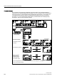
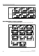
Table 12-12 Example: Replacing a Motor Module
Action Reaction Comments
• Switch off the power supply
• Replace the defective
component and connect the
new one
• Switch on the power supply
Alarm A01425