
- Siemens Cordless Telephone User Manual

Basic information about the drive system
12.4 BICO technology: interconnecting signals
Drive Functions
Function Manual, (FH1), 07/2007 Edition, 6SL3097-2AB00-0BP4
481
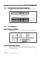
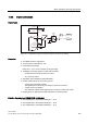
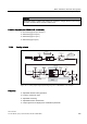
12.4.4 Internal encoding of the binector/connector output parameters
The internal codes are required for writing BICO input parameters via PROFIBUS, for
example.
ELQ ELQELQ
ELQ ELQELQ
KH[ದದ!)HVWHರರ
KH[ದದ!)HVWHರರ
()&KH[ದದ!&2>@
ELQ ELQELQ
3DUDPHWHUQXPEHU
([DPSOHVRIVLJQDOVRXUFHV
,QGH[QXPEHU
'ULYH
REMHFW
'HYLFHHJ&8
6HSDUDWHREMHFW
GHF GHFGHF
%LW ಹಹಹ
Figure 12-6 Internal encoding of the binector/connector output parameters
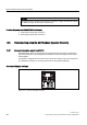
12.4.5 Sample interconnections
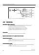
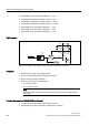
Example 1: Interconnection of digital signals
Suppose you want to operate a drive via terminals DI 0 and DI 1 on the Control Unit using
jog 1 and jog 2.
,QWHUQDO
,QWHUQDO
-RJ
-RJ
-RJ
-RJ
%2%LQHFWRURXWSXW
6LJQDOVRXUFH
%,%LQHFWRULQSXW
6LJQDOVLQN
U
U
',;
',;
S&
S&
9
U
U
',;
',;
S&
S&
9
Figure 12-7 Interconnection of digital signals (example)
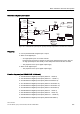
Example 2: Connection of OFF3 to several drives
The OFF3 signal is to be connected to two drives via terminal DI 2 on the Control Unit.
Each drive has a binector input 1. OFF3 and 2. OFF3. The two signals are processed via an
AND gate to STW1.2 (OFF3).