
- Siemens Cordless Telephone User Manual

Communication PROFIBUS DP/PROFINET IO
10.1 Communications according to PROFIdrive
Drive Functions
390 Function Manual, (FH1), 07/2007 Edition, 6SL3097-2AB00-0BP4
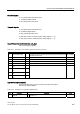
Properties
● No additional parameters need to be entered in addition to the bus configuration in order
to activate this function, the master and slave must only be preset for this function
(PROFIBUS).
● The master-side default setting is made via the hardware configuration, e.g. B. HW
Config with SIMATIC S7. The slave-side default setting is made via the parameterization
telegram when the bus is ramping up.
● Fixed sampling times are used for all data communication.
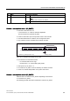
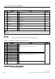
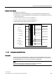
● The Global Control (GC) clock information on PROFIBUS is transmitted before the
beginning of each cycle.
● The length of the clock cycle depends on the bus configuration. When the clock cycle is
selected, the bus configuration tool (e.g. HW Config) supports:
– High number of drives per slave/drive unit -> long cycle
– High number of slaves/drive units -> long cycle
● A sign-of-life counter is used to monitor user data transfer and clock pulse failures.
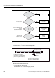
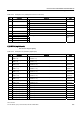
Overview of closed-loop control
● Sensing of the actual position value on the slave can be performed using:
– Indirect measuring system (motor encoder)
– Additional direct measuring system
● The encoder interface must be configured in the process data.
● The control loop is closed via the PROFIBUS.
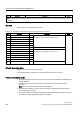
● The position controller is located on the master.
● The current and speed control systems and actual value sensing (encoder interface) are
located on the slave.
● The position controller clock cycle is transmitted across the field bus to the slaves.
● The slaves synchronize their speed and/or current controller cycle with the position
controller cycle on the master.
● The speed setpoint is specified by the master.