
- Siemens Cordless Telephone User Manual

Communication PROFIBUS DP/PROFINET IO
10.1 Communications according to PROFIdrive
Drive Functions
Function Manual, (FH1), 07/2007 Edition, 6SL3097-2AB00-0BP4
387
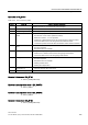
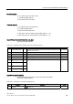
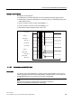
Table 10-24 Description of CU_ZSW (status word for Control Unit)
Bit Meaning Remarks BICO
0...2 Reserved – – –
1 Fault active 3 Fault active
0 No fault present
BO: r2139.3
4...6 Reserved – – –
1 Alarm present 7 Alarm present
0 No alarm present
BO: 2139.7
8 SYNC – – BO: r0899.8
9...11 Reserved – – –
12 Drive unit sign-of-life bit 0 –
13 Drive unit sign-of-life bit 1 –
14 Drive unit sign-of-life bit 2 –
15 Drive unit sign-of-life bit 3 –
Slave sign of life Implicitly
interconnec-
ted
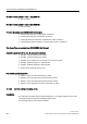
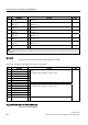
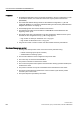
E_DIGITAL (digital inputs)
See function diagram [2459].
Table 10-25 Description of E_DIGITAL (digital inputs)
Bit Meaning Remarks BICO
0 Digital input/output 8
(DI/DO = 8)
– DI/DO 8 on the Control Unit must be parameterized as an input
(p0728.8 = 0).
BO: p0722.8
1 Digital input/output 9
(DI/DO = 9)
– DI/DO 9 on the Control Unit must be parameterized as an input
(p0728.9 = 0).
BO: p0722.9
2 Digital input/output 10
(DI/DO = 10)
– DI/DO 10 on the Control Unit must be parameterized as an input
(p0728.10 = 0).
BO:
p0722.10
3 Digital input/output 11
(DI/DO = 11)
– DI/DO 11 on the Control Unit must be parameterized as an input
(p0728.11 = 0).
BO:
p0722.11
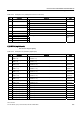
4 Digital input/output 12
(DI/DO = 12)
– DI/DO 12 on the Control Unit must be parameterized as an input
(p0728.12 = 0).
BO:
p0722.12
5 Digital input/output 13
(DI/DO = 13)
– DI/DO 13 on the Control Unit must be parameterized as an input
(p0728.13 = 0).
BO:
p0722.13
6 Digital input/output 14
(DI/DO = 14)
– DI/DO 14 on the Control Unit must be parameterized as an input
(p0728.14 = 0).
BO:
p0722.14
7 Digital input/output 15
(DI/DO = 15)
– DI/DO 15 on the Control Unit must be parameterized as an input
(p0728.15 = 0).
BO:
p0722.15
8 Digital input 0 (DI 0) – Digital input DI 0 on the Control Unit BO: r0722.0
9 Digital input 1 (DI 1) – Digital input DI 1 on the Control Unit BO: r0722.1
10 Digital input 2 (DI 2) – Digital input DI 2 on the Control Unit BO: r0722.2
11 Digital input 3 (DI 3) – Digital input DI 3 on the Control Unit BO: r0722.3
12 Digital input 4 (DI 4) – Digital input DI 4 on the Control Unit BO: r0722.4
13 Digital input 5 (DI 5) – Digital input DI 5 on the Control Unit BO: r0722.5
14 Digital input 6 (DI 6) – Digital input DI 6 on the Control Unit BO: r0722.6
15 Digital input 7 (DI 7) – Digital input DI 7 on the Control Unit BO: r0722.7