
- Siemens Cordless Telephone User Manual


Safety Integrated basic functions
9.10 Overview of parameters and function diagrams
Drive Functions
338 Function Manual, (FH1), 07/2007 Edition, 6SL3097-2AB00-0BP4
9.10 Overview of parameters and function diagrams
Parameter overview (see SINAMICS S List Manual)
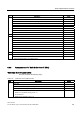
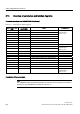
Table 9-13 Parameters for Safety Integrated
No. of Control Unit
(CU)
No. of Motor
Module (MM)
Name Changeable to
p9601 p9801 SI enable safety functions
p9602 p9802 SI enable safe brake control
p9620 - SI signal source for Safe torque off
p9650 p9850 SI SGE changeover, tolerance time (Motor Module)
p9652 p9852 SI Safe Stop 1 delay time
p9658 p9858 SI transition time STOP F to STOP A
p9659 - SI timer for the forced dormant error detection
Safety Integrated
commissioning
(p0010 = 95)
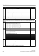
p9761 - SI password input In every operating mode
p9762 - SI password new
p9763 - SI password acknowledgment
Safety Integrated
commissioning
(p0010 = 95)
r9770[0...2] r9870[0...2] SI version safety function integrated in the drive -
r9771 r9871 SI shared functions -
r9772 r9872 SI CO/BO: Status -
r9773 - SI CO/BO: Status (Control Unit + Motor Module) -
r9774 - SI CO/BO: Status (Safe torque off group) -
r9780 r9880 SI monitoring clock cycle -
r9794 r9894 SI crosswise comparison list -
r9795 r9895 SI diagnostics for STOP F -
r9798 r9898 SI actual checksum SI parameters -
p9799 p9899 SI target checksum SI parameters Safety Integrated
commissioning
(p0010 = 95)
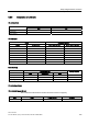
Description of the parameters
Note
The SINAMICS Safety Integrated parameters are described in the following documentation:
References: /LH1/ SINAMICS S List Manual - Section 1.2