
- Siemens Cordless Telephone User Manual


Safety Integrated basic functions
9.5 Safe Brake Control (SBC)
Drive Functions
314 Function Manual, (FH1), 07/2007 Edition, 6SL3097-2AB00-0BP4
&RQWURO
WHUPLQDO
%UDNHGLDJQRVLV
6WDQGE\FXUUHQWEUDNH
0RWRU
7%
&RQWURO8QLW0RWRU
0RGXOH6DIH%UDNH
5HOD\
&RQWUROWHUPLQDO
%5
%5
3
%5
%5
0 0
7%
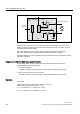
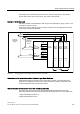
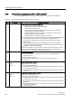
Figure 9-1 Two-channel brake control, booksize
The Motor Module carries out a check to ensure that the "Safe Brake Control" function is
working properly and ensures that, if the Control Unit fails or is faulty, the brake current is
interrupted and the brake applied.
The brake diagnosis can only reliably detect a malfunction in either of the switches
(TB+, TB-) when the status changes (when the brake is released or applied).
If the Motor Module or Control Unit detects a fault, the brake current is switched off and the
safe status is reached.
Response time with the "Safe Brake Control" function
The following values can be specified for the response times when the function is
selected/deselected via input terminals:
● Typical response time
4 x Safety monitoring cycle CU (r9780) + inputs/outputs sampling time (p0799)
● Max. response time in the event of a fault
8 x Safety monitoring cycle CU (r9780) + inputs/outputs sampling time (p0799)
Examples:
Assumption:
Safety monitoring clock cycle time CU (r9780) = 4 ms and
inputs/outputs sampling time (r0799) = 4 ms
t
R_typ
= 4 x r9780 (4 ms) + r0799 (4 ms) = 20 ms
t
R_max
= 8 x r9780 (4 ms) + r0799 (4 ms) = 36 ms