
- Siemens Cordless Telephone User Manual


Monitoring and protective functions
8.5 Thermal motor protection
Drive Functions
Function Manual, (FH1), 07/2007 Edition, 6SL3097-2AB00-0BP4
295
7
)
U
ุ
U
U
0RWRUVWDOOHG
S
V
21GHOD\
0RWRUVWDOOHG
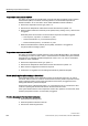
6SHHGDGDSWDWLRQVSHHGGHYLDWLRQ
6SHHGWKUHVKROGVWDOOGHWHFWLRQ
PLQS
S
(UURUWKUHVKROGVWDOOGHWHFWLRQ
)RUVSHHGFRQWUROZLWKHQFRGHURQO\
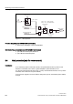
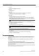
6WDOOPRQLWRULQJ
Figure 8-2 Stall protection
Function diagrams (see SINAMICS S List Manual)
● 6730 Current control
● 8012 Torque messages, motor blocked/stalled
Overview of key parameters (see SINAMICS S List Manual)
● r1408 CO/BO: Control status word 3
● p1744 Motor model speed threshold stall detection
● p1745 Motor model fault threshold value stall detection
● p1755 Motor model without encoder, changeover speed
● p1756 Motor model changeover speed hysteresis
● p2178 Motor stalled delay time
8.5 Thermal motor protection
Description
The priority of thermal motor protection is to identify critical situations. If alarm thresholds are
exceeded, the user can set parameterizable response options (p0610) that enable continued
operation (e.g. with reduced power) and prevent immediate shutdown.
● Effective protection is also possible without a temperature sensor (p4100 = 0). The
temperatures of different motor components (stators, core, rotors) can be determined
indirectly using a temperature model.
● Connecting temperature sensors allows the motor temperature to be determined directly.
In this way, accurate start temperatures are available immediately when the motor is
switched on again or after a power failure.