
- Siemens Cordless Telephone User Manual

Function modules
7.11 Parallel connection of chassis power units (vector)
Drive Functions
290 Function Manual, (FH1), 07/2007 Edition, 6SL3097-2AB00-0BP4
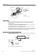
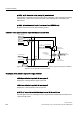
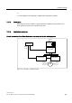
Parallel connection of two Active Line Modules and two Motor Modules on a motor with a single
winding system
89:
$FWLYH/LQH0RGXOH
0RWRU0RGXOH
0RWRU0RGXOH
9ROWDJH
6HQVLQJ
0RGXOH
$FWLYH
,QWHUIDFH
0RGXOH
9ROWDJH
6HQVLQJ
0RGXOH
$FWLYH/LQH0RGXOH
&RQWURO8QLW
'5,9(
&/L4
$FWLYH
,QWHUIDFH
0RGXOH
0
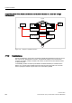
Figure 7-26 Example 2: parallel connection
7.11.5 Commissioning
During commissioning, power units connected in parallel are treated like a power unit on the
line or motor side. With parallel connection, the parameter display for the actual values
changes only slightly. Instead, suitable "total values" are derived from the individual values
for the power units.
In STARTER, parallel connection (Line Modules and Motor Modules) is activated via the
Wizard. You can also select parallel connection when choosing the power unit. You then
have to specify the number of power units to be connected in parallel.