
- Siemens Cordless Telephone User Manual

Infeed
1.1 Active Infeed
Drive Functions
22 Function Manual, (FH1), 07/2007 Edition, 6SL3097-2AB00-0BP4
1.1.2 Active Infeed closed-loop control Booksize
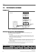
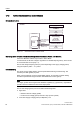
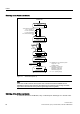
Schematic structure
'&OLQN
/LQHUHDFWRU
$FWLYH,QWHUIDFH
0RGXOH
/LQHILOWHURSWLRQDO
/LQHFRQWDFWRURSWLRQDO
)XVHV
0DLQVZLWFK
0DQLSXODWHGYDULDEOHV
$FWXDOYDOXHV
7HPSHUDWXUHIRU
$FWLYH,QWHUIDFH
0RGXOHV
6XSSO\V\VWHP
9ROWDJH6HQVLQJ
0RGXOHRSWLRQDO
$FWXDO
YDOXHV
%RRNVL]H
'5,9(&/L4
$FWLYH
,QIHHG
)LUPZDUH
&RQWURO8QLW
$FWLYH/LQH0RGXOH
Figure 1-1 Schematic structure of Active Infeed Booksize
Active Infeed closed-loop control for Active Line Modules Booksize
The Active Line Module can be operated in two different modes depending on the
parameterized line supply voltage (p0210):
● Active Mode
In Active Mode, the DC link voltage is regulated to a variable setpoint (p3510), which
results in a sinusoidal line current (cosφ = 1). The level of the reactive current is also
controlled and can be specifically defined.
● Smart Mode
Energy recovery capability is maintained in Smart Mode, although there is a lower DC link
voltage in comparison to the Active Mode. The DC link voltage is dependent on the
current line voltage.
The DC link voltage setpoint (p3510) and the control type are preset as follows during
commissioning in line with the connection voltage (p0210):
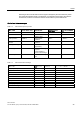
Table 1-1 Presetting the control type and DC link voltage booksize
Supply voltage p0210 [V] 380-400 401-415 416-440 460 480
Control type p3400.0 "0" = Active Mode "1" = Smart Mode
Vdc_soll p3510 [V] 600 625 562-594
1)
621
1)
648
1)