
- Siemens Cordless Telephone User Manual

Vector V/f control (r0108.2 = 0)
5.2 Voltage boost
Drive Functions
Function Manual, (FH1), 07/2007 Edition, 6SL3097-2AB00-0BP4
171
Parameter
values
Meaning Application / property
5 Precise frequency
drives
Characteristic that takes into account the technological particularity of an
application (e.g. textile applications):
a) whereby the current limitation (Imax controller) only affects the output voltage
and not the output frequency, or
b) by disabling slip compensation
6 Precise frequency
drives with flux current
control (FCC)
Characteristic that takes into account the technological particularity of an
application (e.g. textile applications):
a) whereby the current limitation (Imax controller) only affects the output voltage
and not the output frequency, or
b) by disabling slip compensation
Voltage losses in the stator resistance for static / dynamic loads are also
compensated (flux current control FCC). This is particularly useful for small
motors, since they have a relatively high stator resistance.
19 Independent voltage
setpoint
The user can define the output voltage of the Motor Module independently of the
frequency using BICO parameter p1330 via the interfaces (e.g. analog input AI0
of Terminal Board 30 –> p1330 = r4055[0]).
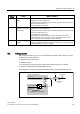
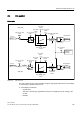
5.2 Voltage boost
With an output frequency of 0 Hz, the V/f characteristics yield an output voltage of 0 V. The
voltage boost must be entered to:
● Magnetize the induction motor.
● Maintain the load.
● Compensate for the losses (ohmic losses in the winding resistors) in the system
● Generate a breakaway/acceleration/braking torque.
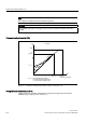
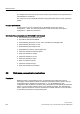
The voltage boost can be increased permanently (p1310) or during acceleration (p1311).
9ROWDJHERRVWDWDFFHOHUDWLRQ
3HUPDQHQWYROWDJHERRVW
5BVWDWRUDFWLYH
0RW,BUDWHG
5DPSXSDFWLYH
9BERRVWSHUP
9BERRVWDFFHOHUDWH
'UY,BRXWSXWPD[
9BERRVWWRWDO
U
S
S
S
S
U
U
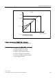
Figure 5-2 Voltage boost total