
- Siemens Cordless Telephone User Manual


Vector control
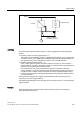
4.20 Bypass
Drive Functions
166 Function Manual, (FH1), 07/2007 Edition, 6SL3097-2AB00-0BP4
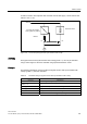
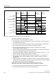
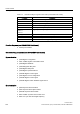
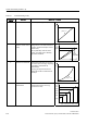
Table 4-10 Parameter setting for bypass function with synchronization with overlap
Parameter Description
p1262 = Bypass dead time setting
p1263 = Debypass dead time setting
p1264 = Bypass delay time setting
p1265 = Speed threshold setting when p1267.1 = 1
p1266 = Control signal setting when p1267.0 = 1
p1267.0 =
p1267.1 =
p1267.2 =
Trigger signal setting for bypass function
P1269[0] = Signal source to provide the feedback signal of contactor K1
P1269[1] = Signal source for contactor K2 feedback
p3800 = 1 The internal voltages are used for synchronization.
p3802 = r1261.2 Synchronizer activation is triggered by the bypass function.
Function diagrams (see SINAMICS S List Manual)
● 7020 Synchronization
Overview of key parameters (see SINAMICS S List Manual)
Bypass function
● p1260 Bypass configuration
● r1261 CO/BO: Bypass control/status word
● p1262 Bypass deadtime
● p1263 Debypass delay time
● p1264 Bypass delay time
● p1265 Bypass speed threshold
● p1266 BI: Bypass control signal
● p1267 Bypass source configuration
● p1268 BI: Bypass control signal
● p1269 BI: Bypass switch feedback signal source
Synchronization
● p3800 Sync-line-drive activation
● p3801 Sync-line-drive object number
● p3802 BI: Sync-line-drive enable
● r3803 CO/BO: Sync-line-drive control word
● r3804 CO: Sync-line-drive target frequency