
- Siemens Cordless Telephone User Manual

Vector control
4.15 Instructions for commissioning permanent-magnet synchronous motors
Drive Functions
150 Function Manual, (FH1), 07/2007 Edition, 6SL3097-2AB00-0BP4
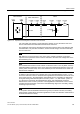
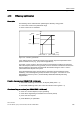
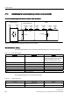
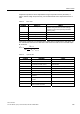
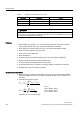
Table 4-7 Equivalent circuit diagram for motor data
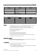
Parameter Description Remark
p0350 Motor stator resistance, cold -
p0356 Motor stator inductance -
p0357 Motor stator inductance, d axis -
WARNING
As soon as the motor starts to rotate, a voltage is generated. When work is carried out on
the converter, the motor must be safely disconnected. If this is not possible, the motor must
be locked by a holding brake, for example.
Features
● Field weakening up to approx. 1.2 * rated speed (this depends on the drive converter
supply voltage and the motor data, also refer to limitations/ constraints)
● Flying restart (for operation without encoder, only possible with additional VSM)
● Vector closed-loop speed and torque control
● Vector V/f control for diagnostics
● Motor identification
● Automatic rotating encoder adjustment (the zero encoder position is calibrated)
● Speed controller optimization (rotating measurement)
● Thermal protection via temperature sensor (PTC/KTY)
● All encoders that can be connected to an SMC10, SMC20 or SMC30 are supported.
● Operation with or without encoder is possible.
Supplementary conditions
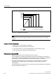
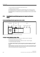
● Maximum speed or maximum torque depend on the converter output voltage available
and the back EMF of the motor (calculation specifications: EMF must not exceed U
rated
converter).
● Calculating the maximum speed:
0RWQRP
0RWQRP
'&OLP
3
,
9
QRPPD[
Q
Q
RU
QRP
'&OLP
N7PLQ
PD[
Q
9
'&OLP
9
9GHYLFHV9
9GHYLFHV9
9GHYLFHV9
ຘ
ຘຘ
˭
ຘ
ຘຘ
V
Calculating k
T
see "Commissioning".