Function Manual 07/2007 SINAMICS S120 Drive Functions SINAMICS S120 sinamics s
Foreword Infeed 1 SINAMICS Extended setpoint channel 2 S120 Drive Functions Servo control 3 Vector control 4 Vector V/f control (r0108.2 = 0) 5 Basic functions 6 Function modules 7 Monitoring and protective functions 8 Safety Integrated basic functions 9 Function Manual Communication PROFIBUS DP/PROFINET IO 10 Applications 11 Basic information about the drive system 12 Appendix Applies to: Firmware version FW2.
Safety Guidelines This manual contains notices you have to observe in order to ensure your personal safety, as well as to prevent damage to property. The notices referring to your personal safety are highlighted in the manual by a safety alert symbol, notices referring only to property damage have no safety alert symbol. These notices shown below are graded according to the degree of danger. DANGER indicates that death or severe personal injury will result if proper precautions are not taken.
Foreword SINAMICS documentation The SINAMICS documentation is organized in 2 parts: ● General documentation / catalogs ● Manufacturer/service documentation A current overview of the documentation in the available languages is provided in the Internet: http://www.siemens.com/motioncontrol Select the menu items "Support" --> "Technical Documentation" --> "Overview of Publications." The Internet version of DOConCD (DOConWEB) is available on the Internet: http://www.automation.siemens.
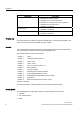
Foreword Usage phase Document/tool Commissioning • • • • • • STARTER parameterization and commissioning tool SINAMICS S120 Getting Started SINAMICS S120 Commissioning Manual SINAMICS S120 CANopen Commissioning Manual SINAMICS S120 Function Manual SINAMICS S List Manual Usage/operation • • SINAMICS S120 Commissioning Manual SINAMICS S List Manual Maintenance/servicing • • SINAMICS S120 Commissioning Manual SINAMICS S List Manual Target group This documentation is intended for machine manufacturer
Foreword Standard scope The scope of the functionality described in this document can differ from the scope of the functionality of the drive system that is actually supplied. ● Other functions not described in this documentation might be able to be executed in the drive system. However, no claim can be made regarding the availability of these functions when the equipment is first supplied or in the event of servicing.
Foreword Questions on the manual Please send any questions about the technical documentation (e.g. suggestions for improvement, corrections) to the following fax number or E-Mail address: Fax: +49 (0) 9131 / 98 - 63315 Email: docu.motioncontrol@siemens.com Fax form: Refer to the reply form at the end of this manual Internet address for SINAMICS http://www.siemens.com/sinamics. EC Declaration of Conformity The EC Declaration of Conformity for the EMC Directive can be obtained from: ● Internet http://www.
Foreword ESD Notes CAUTION Electrostatic sensitive devices (ESD) are single components, integrated circuits or devices that can be damaged by electrostatic fields or electrostatic discharges.
Foreword Safety instructions DANGER • Commissioning must not start until you have ensured that the machine in which the components described here are to be installed complies with Directive 98/37/EC. • SINAMICS devices and AC motors must only be commissioned by suitably qualified personnel. • The personnel must take into account the information provided in the technical customer documentation for the product, and be familiar with and follow the specified danger and warning notices.
Foreword CAUTION • As part of routine tests, SINAMICS devices with AC motors undergo a voltage test in accordance with EN 50178. Before the voltage test is performed on the electrical equipment of industrial machines to EN 60204-1, Section 19.4, all connectors of SINAMICS equipment must be disconnected/unplugged to prevent the equipment from being damaged. • Motors should be connected-up according to the circuit diagram provided. otherwise they can be destroyed.
Contents Foreword ................................................................................................................................................... 5 1 2 3 Infeed ...................................................................................................................................................... 21 1.1 1.1.1 1.1.2 1.1.3 1.1.4 1.1.5 1.1.6 1.1.7 1.1.8 Active Infeed ...........................................................................................................
Contents 4 14 3.4 Torque-controlled operation ........................................................................................................ 69 3.5 Torque setpoint limitation ............................................................................................................ 71 3.6 Current controller ........................................................................................................................ 75 3.7 Current setpoint filter...............................
Contents 5 6 4.18.2 4.18.3 Features .....................................................................................................................................158 Commissioning...........................................................................................................................158 4.19 Redundance operation power units ...........................................................................................158 4.20 4.20.1 4.20.2 4.20.3 Bypass .........................
Contents 7 16 Function modules .................................................................................................................................. 219 7.1 Function modules - Definition and commissioning ................................................................... 219 7.2 7.2.1 7.2.2 7.2.3 7.2.4 7.2.5 Technology controller................................................................................................................ 220 Description ................................
Contents 8 9 10 7.10 DCC axial winder .......................................................................................................................282 7.11 7.11.1 7.11.2 7.11.3 7.11.4 7.11.5 Parallel connection of chassis power units (vector)...................................................................288 Features .....................................................................................................................................288 Integration ........................
Contents 11 18 10.1.3.2 10.1.3.3 10.1.3.4 10.1.3.5 10.1.3.6 10.1.3.7 10.1.4 10.1.4.1 10.1.4.2 10.1.4.3 10.1.4.4 10.1.4.5 Monitoring: telegram failure....................................................................................................... 353 Description of control words and setpoints ............................................................................... 354 Description of status words and actual values..........................................................................
Contents 12 11.4 11.4.1 11.4.2 11.4.3 11.4.4 11.4.5 11.4.6 Application examples with the DMC20 ......................................................................................460 Features .....................................................................................................................................460 Description .................................................................................................................................460 Example, distributed topology....
Contents 12.10.3 12.10.4 12.10.5 12.10.6 12.10.7 12.10.8 Sample wiring for vector drives................................................................................................. 514 Sample wiring of Vector drives connected in parallel ............................................................... 515 Sample wiring: Power Modules................................................................................................. 517 Changing the offline topology in STARTER.............................
1 Infeed 1.1 Active Infeed 1.1.1 Introduction General Note Line Modules (Active Line Modules, Basic Line Modules, Smart Line Modules) of different types must not be operated simultaneously on the same DC link.
Infeed 1.1 Active Infeed 1.1.
Infeed 1.1 Active Infeed Supply voltage p0210 [V] 380-400 401-415 416-440 460 480 Voltages specified for the smart mode are derived from the rectified line supply voltage. The DC link voltage setpoint (p3510) has no effect in this control mode.
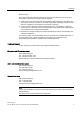
Infeed 1.1 Active Infeed 1.1.3 Active Infeed closed-loop control Chassis Schematic structure &KDVVLV 6XSSO\ V\VWHP 0DLQ VZLWFK )XVHV &RQWURO 8QLW )LUPZDUH 6XSSO\ V\VWHP GDWD $FWLYH ,QIHHG $FWLYH ,QWHUIDFH 0RGXOH ZLWK SUHFKDUJLQJ ZLWK 960 :LWK OLQH ILOWHU ZLWK OLQH UHDFWRU 0DQLSXODWHG YDULDEOHV $FWXDO YDOXHV $FWLYH /LQH 0RGXOH '5,9( &/L4 Figure 1-2 '& OLQN Schematic structure of Active Infeed Operating mode of Active Infeed closed-loop control for Chassis Active Line Modules.
Infeed 1.1 Active Infeed 1.1.4 Integration Function diagrams (see SINAMICS S List Manual) ● 1774 Overviews - Active Infeed ● 8920 Control word sequential control infeed ● ...
Infeed 1.1 Active Infeed 1.1.5 Line and DC link identification The characteristic line supply and DC link quantities are determined using the automatic parameter identification routine. They provide the basis to optimally set the controllers in the Line Module. An optimal setting of the current and voltage control is achieved with the help of the line supply and DC link identification routine. The dynamic response of the current control can be adjusted with p3560.
Infeed 1.1 Active Infeed 1.1.6 Active Infeed open-loop control Description The Active Line Module can be controlled via the BICO interconnection by means of terminals or the field bus. The operating status is indicated on the operating display r0002. The missing enable signals for operation (r0002 = 00) are mapped in parameter r0046. The EP terminals (enable pulses) must be connected in accordance with the Equipment Manual. The drive unit must have been commissioned for the first time.
Infeed 1.
Infeed 1.1 Active Infeed Switching off the controller with the OFF1 signal is delayed by the time entered in p3490. This allows the attached drives to be braked in a controlled manner. Before the infeed is switched off, the drives connected to the DC link should be in pulse inhibit mode. Control and status messages Table 1-2 Active Infeed open-loop control Signal name Internal control word Binector input Display of internal control word PROFIdrive telegram 370 ON/OFF1 STWAE.0 p0840 ON/OFF1 r0898.
Infeed 1.1 Active Infeed 1.1.7 Reactive current control A reactive current setpoint can be set to compensate the reactive current or to stabilize the line voltage in infeed mode. The total setpoint is the sum of the fixed setpoint p3610 and the dynamic setpoint via the connector input p3611. Note The direction of rotation of the network is compensated automatically with reactive current control.
Infeed 1.2 Smart Infeed Overview: key parameters ● p3624 Infeed harmonics controller order ● p3625 Infeed harmonics controller scaling ● r0069[0..6] Phase current, actual value 1.2 Smart Infeed 1.2.1 Smart Infeed closed-loop control General Note Line Modules (Active Line Modules, Basic Line Modules, Smart Line Modules) of different types must not be operated simultaneously on the same DC link.
Infeed 1.
Infeed 1.2 Smart Infeed Note In a supply system without regenerative feedback capability (e.g. generators), regenerative operation must be inhibited via the binector input p3533.
Infeed 1.2 Smart Infeed Note If the line supply environment changes, or the components connected to the DClink (e.g. after installing and mounting the equipment at the customer's site or after expanding the drive group), then the line supply/DC link identification routine should be repeated with p3410 = 5. Only then can it be guaranteed that the infeed operates with an optimum controller setting. When the identification function is activated, alarm A06400 is output.
Infeed 1.2 Smart Infeed 1.2.3 Smart Infeed open-loop control Description The Smart Line Module can be controlled via the BICO interconnection by means of terminals or the field bus. The operating status is indicated on the operating display r0002. The missing enable signals for operation (r0002 = 00) are mapped in parameter r0046. The EP terminals (enable pulses) must be connected in accordance with the Equipment Manual. The drive unit must have been commissioned for the first time.
Infeed 1.
Infeed 1.2 Smart Infeed Note Under the condition that the drive system was commissioned with STARTER and no PROFIdrive telegram was activated, the infeed can be powered-up by issuing an enable signal at the EP terminals and a positive signal edge at OFF1 (p0840). Switching off the Smart Line Module To switch off the Active Line Module, carry out the steps for switching it on in reverse order. Switching off the controller with the OFF1 signal is delayed by the time entered in p3490.
Infeed 1.3 Basic Infeed Signal name Internal status word Parameter PROFIdrive telegram 370 Pre-charging completed ZSWAE.11 r0899.11 A_ZSW1.11 Line contactor energized feedback ZSWAE.12 r0899.12 A_ZSW1.12 1.3 Basic Infeed 1.3.1 Basic Infeed open-loop control General Note Line Modules (Active Line Modules, Basic Line Modules, Smart Line Modules) of different types must not be operated simultaneously on the same DC link.
Infeed 1.
Infeed 1.3 Basic Infeed If a braking resistor has not been connected for 20 kW and 40 kW Basic Line Modules Booksize, the braking chopper must be deactivated via p3680 = 1. Function diagrams (see SINAMICS S List Manual) ● 8720 Control word sequential control infeed ● ...
Infeed 1.
Infeed 1.4 Line contactor control Control and status messages Table 1-7 Basic Infeed open-loop control Signal name Internal control word Binector input Display of internal control word PROFIdrive telegram 370 ON/OFF1 STWAE.0 p0840 ON/OFF1 r0898.0 A_STW1.0 OFF2 STWAE.1 p0844 1 OFF2 and p0845 2 OFF2 r0898.1 A_STW1.1 Acknowledge error STWAE.7 p2103 1 Acknowledge or p2104 2 Acknowledge or p2105 3 Acknowledge r2138.7 A_STW1.7 Master ctrl by PLC STWAE.10 p0854 Master ctrl by PLC r0898.
Infeed 1.
Infeed 1.5 Pre-charging and bypass contactor chassis Function diagrams (see SINAMICS S List Manual) ● 8934 Missing enables, line contactor control Overview of key parameters (see SINAMICS S List Manual) ● r0863.1 CO/BO: Drive coupling status word/control word ● p0860 BI: Line contactor, feedback signal 1.5 Pre-charging and bypass contactor chassis Description Pre-charging is the procedure for charging the DC link capacitors via resistors.
Infeed 1.6 Derating function for chassis units 1.6 Derating function for chassis units Description An adjusted derating function can greatly reduce the noise level during the operation of the chassis power units (Motor and Power Modules) and enable operation at a multiple of the nominal pulse frequency at nearly nominal current. This is achieved by monitoring the temperature increase between heat-sink and chip by means of temperature sensors.
Infeed 1.7 Parallel connections of 6-pulse and 12-pulse chassis infeeds 1.7 Parallel connections of 6-pulse and 12-pulse chassis infeeds Description With Basic Line Modules and chassis units, in addition to 6-pulse parallel infeed (infeed via two-winding transformer), it is also possible to use a 12-pulse parallel infeed (infeed via three-winding transformer).
Extended setpoint channel 2 Description In the servo operating mode, the extended setpoint channel is deactivated by default. If an extended setpoint channel is required, it has to be activated. Properties of servo mode without the "extended setpoint channel" function module ● The setpoint is directly interconnected to p1155[D] (e.g.
Extended setpoint channel 2.2 Description 2.2 Description In the extended setpoint channel, setpoints from the setpoint source are conditioned for motor control. The setpoint for motor control can also originate from the technology controller (see "Technology controller").
Extended setpoint channel 2.3 Jog ● Jog ● Field bus – Setpoint via PROFIBUS, for example ● Via the analog inputs of the following exemplary components: – e.g. Terminal Board 30 (TB30) – e.g. Terminal Module 31 (TM31) – e.g. Terminal Module 41 (TM41) 2.3 Jog Description This function can be selected via digital inputs or via a field bus (e.g. PROFIBUS). The setpoint is, therefore, predefined via p1058[D] and p1059[D].
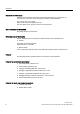
Extended setpoint channel 2.3 Jog -RJ S 'LJLWDO LQSXW )LHOG EXV W -RJ S W Q S S Figure 2-3 S S S S S S W Function chart: jog 1 and jog 2 Jog properties ● If both jog signals are issued at the same time, the current speed is maintained (constant velocity phase). ● Jog setpoints are approached and exited via the ramp-function generator.
Extended setpoint channel 2.
Extended setpoint channel 2.3 Jog Control and status messages Table 2-1 Jog control Signal name Internal control word Binector input PROFIdrive/Siemens telegram 1 ... 116 0 = OFF1 STWA.0 p0840 ON/OFF1 STW1.0 0 = OFF2 STWA.1 p0844 1. OFF2 p0845 2. OFF2 STW1.1 0 = OFF3 STWA.2 p0848 1. OFF3 p0849 2. OFF3 STW1.2 Enable operation STWA.3 p0852 Enable operation STW1.3 Jog 1 STWA.8 p1055 Jog bit 0 STW1.8 Jog 2 STWA.9 p1056 Jog bit 1 STW1.
Extended setpoint channel 2.4 Fixed speed setpoints 2.4 Fixed speed setpoints Description This function can be used to specify preset speed setpoints. The fixed setpoints are defined in parameters and selected via binector inputs. Both the individual fixed setpoints and the effective fixed setpoint are available for further interconnection via a connector output (e.g. to connector input p1070 - CI: main setpoint).
Extended setpoint channel 2.5 Motorized potentiometer Parameterization with STARTER In the STARTER commissioning tool, the "Fixed setpoints" parameter screen in the project navigator under the relevant drive is activated by double-clicking Setpoint channel -> Fixed setpoints. 2.5 Motorized potentiometer Description This function is used to simulate an electromechanical potentiometer for setpoint input. You can switch between manual and automatic mode for setpoint input.
Extended setpoint channel 2.5 Motorized potentiometer – Setting value (p1043/p1044) – Initial rounding-off active/not active (p1030.2) ● Non-volatile storage of the setpoints via p1030.3 ● Configurable setpoint for Power On (p1030.0) – Starting value is the value in p1040 (p1030.0 = 0) – Starting value is the stored value (p1030.
Extended setpoint channel 2.6 Main/supplementary setpoint and setpoint modification 2.6 Main/supplementary setpoint and setpoint modification Description The supplementary setpoint can be used to incorporate correction values from lower-level controllers. This can be easily carried out using the addition point for the main/supplementary setpoint in the setpoint channel. Both variables are imported simultaneously via two separate or one setpoint source and added in the setpoint channel.
Extended setpoint channel 2.7 Direction of rotation limiting and direction of rotation changeover Display parameters r1073[C] CO: Main setpoint effective r1077[C] CO: Supplementary setpoint effective r1078[C] CO: Total setpoint effective Parameterization with STARTER The "Speed setpoint" parameter screen is selected with the STARTER commissioning tool: 2.
Extended setpoint channel 2.
Extended setpoint channel 2.
Extended setpoint channel 2.9 Ramp-function generator ● p1088[C] DI: Speed limit negative direction of rotation ● r1119 Ramp-function generator setpoint at the input Suppression bandwidths ● p1091[D] Suppression speed 1 ● ... ● p1094[D] Suppression speed 4 ● p1101[D] Suppression speed bandwidth Parameterization with STARTER The "speed limitation" parameter screen is selected by activating the following icon in toolbar of the STARTER commissioning tool: Figure 2-8 2.
Extended setpoint channel 2.
Extended setpoint channel 2.
Extended setpoint channel 2.
Extended setpoint channel 2.
3 Servo control This type of closed-loop control enables operation with a high dynamic response and precision for a motor with a motor encoder. 3.1 Speed controller The speed controller controls the motor speed using the actual values from the encoder (operation with encoder) or the calculated actual speed value from the electric motor model (operation without encoder). Properties ● Speed setpoint filter ● Speed controller adaptation Note Speed and torque cannot be controlled simultaneously.
Servo control 3.2 Speed setpoint filter 3.2 Speed setpoint filter The two speed setpoint filters are identical in structure and can be used as follows: ● Bandstop ● Low-pass 1st order (PT1) or ● Low-pass 2nd order (PT2) Both filters are activated via parameter p1414.x. Parameters p1415 and p1421 are used to select the filter elements.
Servo control 3.3 Speed controller adaptation ● p1425[DDS] Speed setpoint filter 2 numerator natural frequency ● p1426[DDS] Speed setpoint filter 2 numerator damping Parameterization In the STARTER commissioning tool, the "Speed setpoint filter" parameter screen is icon in the toolbar: selected with the 3.3 Speed controller adaptation Description Two adaptation methods are available, namely free Kp_n adaptation and speed-dependent Kp_n/Tn_n adaptation.
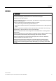
Servo control 3.3 Speed controller adaptation Example of speed-dependent adaptation Note This type of adaptation is only active in "operation with encoder" mode. .SBQ 7QBQ 3URSRUWLRQDO JDLQ ,QWHJUDO WLPH S [ S S .
Servo control 3.4 Torque-controlled operation ● p1458[0...n] Lower adaptation factor ● p1459[0...n] Upper adaptation factor Speed-dependent Kp_n/Tn_n adaptation ● p1460[0...n] Speed controller P gain lower adaptation speed ● p1461[0...n] Speed controller Kp adaptation speed upper scaling ● p1462[0...n] Speed controller integral time lower adaptation speed ● p1463[0...n] Speed controller Tn adaptation speed upper scaling ● p1464[0...n] Speed controller lower adaptation speed ● p1465[0...
Servo control 3.4 Torque-controlled operation U S >&@ H J S > @ S >&@ S >&@ Figure 3-6 Torque setpoint 3. Activate enable signals OFF responses ● OFF1 and p1300 = 23 – Reaction as for OFF2 ● OFF1, p1501 = "1" signal and p1300 ≠ 23 – No separate braking response; the braking response takes place by a drive that specifies the torque. – The pulses are suppressed when the brake application time (p1217) expires.
Servo control 3.5 Torque setpoint limitation Function diagrams (see SINAMICS S List Manual) ● 5060 Torque setpoint, control type switchover ● 5610 Torque limiting/reduction/interpolator Signal overview (see SINAMICS S List Manual) ● r1406.
Servo control 3.
Servo control 3.5 Torque setpoint limitation Fixed and variable torque limit settings Table 3-1 Fixed and variable torque limit settings Selection Torque limitation mode Mode Maximum upper or lower torque limits p1400.4 = 0 Maximum motor or regenerative mode torque limits p1400.
Servo control 3.5 Torque setpoint limitation Example: Torque limits with or without offset The signals selected via p1522 and p1523 include the torque limits parameterized via p1520 and p1521. 0 0 S S S S S S 0BRIIVHW S Figure 3-9 0BRIIVHW ! S Example: Torque limits with or without offset Activating the torque limits 1. Use parameters to select the torque limitation source. 2. Use a control word to specify the torque limitation mode. 3.
Servo control 3.6 Current controller Overview of key parameters (see SINAMICS S List Manual) ● p0640[0...n] Current limit ● p1400[0...n] Speed control configuration ● r1508 CO: Torque setpoint before supplementary torque ● r1509 CO: Torque setpoint before torque limiting ● r1515 Supplementary torque total ● p1520[0...n] CO: Torque limit, upper/motoring ● p1521[0...
Servo control 3.6 Current controller Closed-loop current control No settings are required for operating the current controller. Optimization measures can be taken in certain circumstances. Current and torque limitation The current and torque limitations are initialized when the system is commissioned for the first time and should be adjusted according to the application.
Servo control 3.6 Current controller Overview of key parameters (see SINAMICS S List Manual) Closed-loop current control ● p1701[0...n] Current controller reference model dead time ● p1715[0...n] Current controller P gain ● p1717[0...n] Current controller integral time Current and torque limitation ● p0323[0...n] Maximum motor current ● p0326[0...n] Stall torque correction factor ● p0640[0...n] Current limit ● p1520[0...n] CO: Torque limit, upper/motoring ● p1521[0...
Servo control 3.7 Current setpoint filter Current controller adaptation ● p0391[0...n] Current controller adaptation lower starting point ● p0392[0...n] Current controller adaptation upper starting point ● p0393[0...n] Current controller adaptation upper P gain ● p1590[0...n] Flux controller P gain ● p1592[0...n] Flux controller integral time 3.
Servo control 3.
Servo control 3.7 Current setpoint filter Table 3-2 Example of a PT2 filter STARTER filter parameters Amplitude log frequency curve Characteristic frequency fN 500 Hz Damping DN 0.
Servo control 3.7 Current setpoint filter Band-stop with defined notch depth Table 3-4 Example of band-stop with defined notch depth STARTER filter parameters Amplitude log frequency curve Blocking frequency fSp = 500 Hz Bandwidth fBB = 500 Hz Notch depth K = -20 dB Reduction Abs = 0 dB Phase frequency curve . G% Simplified conversion to parameters for general order filters: No reduction or increase after the blocking frequency Defined notch at the blocking frequency K[dB] (e.g.
Servo control 3.7 Current setpoint filter ● Denominator natural frequency ˶1 = I 6S ˭ $EV I %% ' 1 ● Denominator damping I 1 I 6S $EV General low-pass with reduction Table 3-6 Example of general low-pass with reduction STARTER filter parameters Amplitude log frequency curve Characteristic frequency fAbs = 500 Hz Damping D = 0.
Servo control 3.7 Current setpoint filter Table 3-7 Example of general 2nd order filter STARTER filter parameters Amplitude log frequency curve Numerator frequency fZ = 500 Hz Numerator damping DZ = 0.02 dB Denominator frequency fN = 900 Hz Denominator damping DN = 0.
Servo control 3.8 Note about the electronic motor model 3.8 Note about the electronic motor model A model change takes place within the speed range p1752*(100%-p1756) and p1752. With induction motors with encoder, the torque image is more accurate in higher speed ranges; the effect of the rotor resistance and the saturation of the main field inductance are corrected. With synchronous motors with encoder, the commutation angle is monitored.
Servo control 3.9 V/f control for diagnostics Structure of V/f control S Q I 5DPS IXQFWLRQ JHQHUDWRU S S S 8 S S Figure 3-14 Structure of V/f control Prerequisites for V/f control 1. Initial commissioning has been carried out: The parameters for V/f control have been initialized with appropriate values. 2.
Servo control 3.9 V/f control for diagnostics V/f characteristic The speed setpoint is converted to the frequency specification taking into account the number of pole pairs. The synchronous frequency associated with the speed setpoint is output (no slip compensation).
Servo control 3.10 Optimizing the current and speed controller 3.10 Optimizing the current and speed controller General information CAUTION Controller optimization may only be performed by skilled personnel with a knowledge of control engineering.
Servo control 3.11 Sensorless operation (without an encoder) Example of measuring the speed controller frequency response By measuring the speed controller frequency response and the control system, critical resonance frequencies can, if necessary, be determined at the stability limit of the speed control loop and dampened using one or more current setpoint filters. This normally enables the proportional gain to be increased (e.g. Kp_n = 3* default value).
Servo control 3.11 Sensorless operation (without an encoder) Since the dynamic response in operation without an encoder is lower than in operation with an encoder, accelerating torque pre-control is implemented to improve the control dynamic performance.
Servo control 3.11 Sensorless operation (without an encoder) be enabled. A large discrepancy between the actual and setpoint speed can cause a malfunction. WARNING Once the pulses have been canceled, no information about the motor speed is available. The computed actual speed value is then set to zero, which means that all actual speed value messages and output signals are irrelevant.
Servo control 3.11 Sensorless operation (without an encoder) Series reactor When high-speed special motors are used, or other low leakage induction motors, a series reactor may be required to ensure stable operation of the current controller. The series reactor can be integrated via p0353. Commissioning/optimization 1. Estimate the motor current p1612 on the basis of the mechanical conditions (I = M/kt). 2. Set Kn (p1470) and Tn (p1472) above I/f operation (> p1755).
Servo control 3.12 Motor data identification 3.12 Motor data identification Description The motor data identification (MotID) is used as tool to determine the motor data, e.g. of third-party motors and can help to improve the torque accuracy (kT estimator). The drive system must have been commissioned for the first time as basis for using MotID.
Servo control 3.12 Motor data identification DANGER The stationary MotID can result in slight movement of up to 210 degrees electrical. For the rotating motor data identification routine, motor motion is initiated, which can reach the maximum speed (p1082) and the motor torque corresponding to the maximum current (p0640).
Servo control 3.
Servo control 3.
Servo control 3.12 Motor data identification Determined data (gamma) Data that are accepted (p1960 = 1) Note: The magnetic design of the motor can be identified from the saturation characteristic.
Servo control 3.12 Motor data identification Table 3-14 Data determined using p1960 for synchronous motors (rotating measurement) Determined data Data that are accepted (p1960 = 1) r1934 q inductance identified - r1935 q inductance identification current - Note: The q inductance characteristic can be used as basis to manually determine the data for the current controller adaptation (p0391, p0392 and p0393).
Servo control 3.
Servo control 3.
Servo control 3.13 Pole position identification WARNING Before using the pole position identification routine, the control sense of the speed control loop must be corrected (p0410.0). For linear motors, refer to the Commissioning Manual. For rotating motors, in sensorless operation with a small positive speed setpoint (e.g. 10 RPM), the speed actual value (r0061) and the speed setpoint (r1438) must have the same sign.
Servo control 3.
Servo control 3.14 Vdc control Angular commutation offset commissioning support (p1990) The function for determining the commutation angle offset is activated via p1990=1. The commutation angle offset is entered in p0431. This function can be used in the following cases: ● Single calibration of the pole position for encoders with absolute information (exception: The Hall sensor must always be mechanically adjusted.
Servo control 3.14 Vdc control significant enough. The motors may no longer be able to maintain their setpoint speed or the acceleration/braking phases are prolonged. The Vdc controller is an automatic P controller that influences the torque limits. It only intervenes when the DC link voltage approaches the "upper threshold" (p1244) or "lower threshold" (p1248) and the corresponding controller is activated via the configuration parameter (p1240). The recommended setting for the P gain is p1250 = 0.
Servo control 3.14 Vdc control can be used to maintain the DC link voltage. The threshold should be considerably higher than the shutdown threshold of the Motor Modules (recommendation: 50 V below the DC link voltage). When the power supply is reestablished, the Vdc controller is automatically deactivated and the drives approach the speed setpoint again.
Servo control 3.14 Vdc control feed energy back, the drives with an active Vdc_max controller can even be accelerated to absorb the braking energy and, in turn, relieve the DC link. Description of Vdc_max control without acceleration (p1240 = 7, 9) As with p1240 = 1, 3, if the drive must not be accelerated by means of feedback from other drives in the DC link, acceleration can be prevented by the setting p1240 = 7, 9.
Servo control 3.15 Dynamic Servo Control (DSC) 3.15 Dynamic Servo Control (DSC) Description The function Dynamic Servo Control" (DSC) is a closed-loop control structure which is computed in a fast speed controller clock cycle and is supplied with setpoints by the control in the position controller clock cycle. This allows higher position controller gain factors to be achieved.
Servo control 3.15 Dynamic Servo Control (DSC) 'DWD WUDQVIHU GHDGWLPH ,QWHUSRODWRU Q SUH Q SUH )3 )3 3DWK LQWHUSRODWLRQ 'DWD WUDQVIHU GHDGWLPH 7SRVLWLRQ [VHW ,QWHUSRODWRU .
Servo control 3.15 Dynamic Servo Control (DSC) Speed setpoint filter A speed setpoint filter to smoothen the speed setpoint steps is no longer required when DSC is active. When using the "DSC" function, it only makes sense to use speed setpoint filter 1 to support the position controller, e.g. to suppress resonance effects.
Servo control 3.16 Travel to fixed stop Overview of key parameters (see SINAMICS S List Manual) ● p1190 CI: DSC position deviation XERR ● p1191 CI: DSC position controller gain KPC ● p1192[DDS] DSC encoder selection ● p1193[DDS] DSC encoder adaptation factor ● r1407.4 CO/BO: Status word, velocity controller 3.16 Travel to fixed stop Description This function can be used to move a motor to a fixed stop at a specified torque without a fault being signaled.
Servo control 3.
Servo control 3.16 Travel to fixed stop Signal chart 0BOLPLW 0BDFW QBVHWS S $OVR IRU 352),GULYH WRUTXH WHOHJUDPV WR UHGXFWLRQ S 7UDYHO WR IL[HG VWRS U )L[HG VWRS UHDFKHG WRUTXH OLPLW UHDFKHG U 7RUTXH XWLOL]DWLRQ S Figure 3-25 Signal chart for "Travel to fixed stop" Commissioning for PROFIdrive telegrams 2 to 6 1. Activate travel to fixed stop. Set p1545 = "1". 2. Set the required torque limit. Example: p1400.
Servo control 3.16 Travel to fixed stop The motor runs at the set torque until it reaches the stop and continues to work against the stop until the torque limit has been reached, this status being indicated in status bit r1407.7 "Torque limit reached". Control and status messages Table 3-16 Control: Travel to fixed stop Signal name Activates travel to fixed stop Table 3-17 Internal control word STW n_ctrl 8 Binector input p1545 Activates travel to fixed stop PROFIdrive p0922 and/or p2079 STW2.
Servo control 3.17 Vertical axes ● p1545[0...n] BI: Activates travel to fixed stop ● p2194[0...n] Torque threshold 2 ● p2199.11 BO: Torque utilization < torque threshold value 2 3.17 Vertical axes Description With a vertical axis without mechanical weight compensation, electronic weight compensation can be set by offsetting the torque limits (p1532). The torque limits specified in p1520 and p1521 are shifted by this offset value. The offset value can be read in r0031 and transferred in p1532.
Vector control 4 Compared with vector V/f control, vector control offers the following benefits: ● Stability vis-à-vis load and setpoint changes ● Short rise times with setpoint changes (–> better command behavior) ● Short settling times with load changes (–> better disturbance characteristic) ● Acceleration and braking are possible with maximum available torque ● Motor protection due to variable torque limitation in motor and regenerative mode ● Drive and braking torque controlled independently of the sp
Vector control 4.1 Sensorless vector control (SLVC) _ IBDFW _ S >530@ S >530@ p1756 ⎞ ⎛ • ⎜⎜ 1− ⎟ 100% ⎟⎠ ⎝ W 2SHQ FRQWURO ORRS &ORVHG FRQWURO ORRS W p1758 Figure 4-1 Switchover conditions for SLVC In open-loop operation, the calculated actual speed value is the same as the setpoint value.
Vector control 4.1 Sensorless vector control (SLVC) I 6WDUW I =HUR FURVVRYHU &ORVHG ORRS &ORVHG ORRS S S 2SHQ ORRS 2SHQ ORRS W W S Figure 4-2 Start-up and passing through 0 Hz in closed-loop operation Closed-loop operation up to approx.
Vector control 4.2 Vector control with encoder I 0 6WDUW =HUR WUDQVLWLRQ I 0 I I S S FRQWUROOHG FRQWUROOHG 0VHW U 0VHW U W W S S Figure 4-3 Zero crossover for permanent-magnet synchronous motors Function diagrams (see SINAMICS S List Manual) ● 6730 Interface with Motor Module for induction motor (p0300 = 1) ● 6731 Interface to the Motor Module (PEM, p0300 = 2) Overview of key parameters (see SINAMICS S List Manual) ● p0305[0...
Vector control 4.3 Speed controller ● Compared with speed control without an encoder, the dynamic response of drives with an encoder is significantly better because the speed is measured directly and integrated in the model created for the current components. ● Higher speed accuracy Motor model change A model change takes place between the current model and the observer model within the speed range p1752*(100%-p1756) and p1752. In the current model range (i.
Vector control 4.3 Speed controller 'URRS LQMHFWLRQ U U 3UH FRQWURO 6SHHG FRQWURO U . S U 6SHHG VHWSRLQW U 7 Q 3, 6SHHG FRQWUROOHU U > @ U U 7RUTXH 7 L U VHWSRLQW 6/9& 7 L S .
Vector control 4.4 Speed controller adaptation Note In comparison with speed control with an encoder, the dynamic response of drives without an encoder is significantly reduced. The actual speed is derived by means of a model calculation from the converter output variables for current and voltage that have a corresponding interference level. To this end, the actual speed must be adjusted by means of filter algorithms in the software.
Vector control 4.4 Speed controller adaptation S S \ $GDSWDWLRQ VLJQDO S [ UHIHUUHG WR S [ RU S [ $GDSWDWLRQ VLJQDO S [ S S S S S .SBQBDGDSW 6SHHG GHSHQGHQW S .
Vector control 4.4 Speed controller adaptation .SBQ 7QBQ 3URSRUWLRQDO JDLQ ,QWHJUDO WLPH S [ S S .
Vector control 4.
Vector control 4.5 Speed controller pre-control and reference model 'URRS LQMHFWLRQ $FFHOHUDWLRQ SUHFRQWURO - p1400.
Vector control 4.5 Speed controller pre-control and reference model Note The ramp-up and ramp-down times (p1120; p1121) of the ramp function generator in the setpoint channel should be set accordingly so that the motor speed can track the setpoint during acceleration and braking. This ensures that speed controller pre-control is functioning optimally. The acceleration pre-control using a connector input (p1495) is activated by the parameter settings p1400.2 = 1 and p1400.3 = 0.
Vector control 4.6 Droop The reference model can also be emulated externally and its output signal injected via p1437. Function diagrams (see SINAMICS S List Manual) ● 6031 Pre-control balancing for reference/acceleration model ● 6040 Speed controller Overview of key parameters (see SINAMICS S List Manual) ● p0311[0...n] Rated motor speed ● r0333[0...n] Rated motor torque ● p0341[0...n] Motor moment of inertia ● p0342[0...n] Ratio between the total moment of inertia and that of the motor ● r0345[0...
Vector control 4.6 Droop S 'URRS LQMHFWLRQ S U PV U U S 3UH FRQWURO U 7Q .S 3, U > @ 7RUTXH 6SHHG VHWSRLQW U U U FRQWUROOHU 7RUTXH 7L U > @ U VHWSRLQW 6HWSRLQW $FWXDO VSHHG 2QO\ DFWLYH LI SUH FRQWURO LV DFWLYH S ! 2QO\ DFWLYH ZLWK 6/9& Figure 4-10 7L .
Vector control 4.7 Torque control Overview of key parameters (see SINAMICS S List Manual) ● p1488[0...n] Droop input source ● p1489[0...n] Droop feedback scaling ● p1492[0...n] BI: Droop feedback enable ● r1482 CO: Speed controller I torque output ● r1490 CO: Droop feedback speed reduction 4.7 Torque control With sensorless speed control SLVC (p1300 = 20) or speed control with sensor VC (p1300 = 21), a switchover can be made to torque control (slave drive) via BICO parameter p1501.
Vector control 4.7 Torque control Kp - 6SHHG VHWSRLQW Tn 3, VSHHG FRQWUROOHU Ti r1547[0] r1538 r0079 r1539 7RUTXH VHWSRLQW 0 1 r1547[1] 6SHHG DFWXDO YDOXH 0BVHW p1503[C] (0) S 0 5HJ 1 p1501 0BUHJ DFWLYH [FP2520.7] r1406.12 0BVXSSO r1407.
Vector control 4.7 Torque control ● OFF2 – Immediate pulse suppression, the drive coasts to standstill. – The motor brake (if parameterized) is closed immediately. – Power-on disable is activated. ● OFF3 – Switch to speed-controlled operation – n_set = 0 is input immediately to brake the drive along the OFF3 deceleration ramp (p1135). – When zero speed is detected, the motor brake (if parameterized) is closed. – The pulses are suppressed when the motor brake application time (p1217) has elapsed.
Vector control 4.8 Torque limiting 4.8 Torque limiting Description S S 7RUTXH OLPLWV U U 0LQ U U S S S Figure 4-12 &XUUHQW OLPLW 0D[ 3RZHU OLPLWV U U Torque limiting The value specifies the maximum permissible torque whereby different limits can be parameterized for motor and regenerative mode. ● p0640[0...n] Current limit ● p1520[0...n] CO: Torque limit, upper/motoring ● p1521[0...n] CO: Torque limit, lower/regenerative ● p1522[0...
Vector control 4.9 Vdc control setpoint is limited in the Motor Module, this is indicated via the following diagnostic parameters: ● r1407.8 Upper torque limit active ● r1407.9 Lower torque limit active indicated. Function diagrams (see SINAMICS S List Manual) ● 6060 Torque setpoint ● 6630 Upper/lower torque limit ● 6640 Current/power/torque limits 4.9 Vdc control Description Vdc_ctrl Tn p1251 Vdc_max Vdc_ctrl Kp p1250 Vdc_ctrl config p1240 Vdc_max on_level r1242 Vdc_ctrl t_deriv.
Vector control 4.9 Vdc control The "Vdc control" function can be activated using the appropriate measures if an overvoltage or undervoltage is present in the DC link. ● Overvoltage in the DC link – Typical cause The drive is operating in regenerative mode and is supplying too much energy to the DC link. – Remedy Reduce the regenerative torque to maintain the DC link voltage within permissible limits.
Vector control 4.9 Vdc control Description of Vdc_min control 3RZHU UHVWRUH 3RZHU IDLOXUH U ZLWKRXW .,3 IDXOW ) 9 W 9GF FWUO DFWLYH W QVHWS ZLWKRXW SRZHU UHVWRUH IDXOW ) 530 ,TVHWS $ 73RZHU IDLOXUH W W PRWRU UHJHQHUDWLYH Figure 4-14 Switching Vdc_min control on/off (kinetic buffering) In the event of a power failure, Vdc_min control is activated when the Vdc_min switch-in level is undershot. This controls the DC link voltage and maintains it at a constant level.
Vector control 4.9 Vdc control Description of Vdc_max control >9@ 6ZLWFK RQ OHYHO 9GF 9GF FWUO DFWLYH W W _Q_ QDFW QVHWS W ,TVHWS $ ,TVHWS WRUTXH JHQHUDWLQJ FXUUHQW VHWSRLQW Figure 4-15 Switching Vdc_max control on/off The switch-in level for Vdc_max control (r1242) is calculated as follows: ● When the function for automatically detecting the switch-on level is switched off (p1254 = 0) r1242 = 1.15 * p0210 (device connection voltage, DC link).
Vector control 4.10 Current setpoint filter ● p1256[0...n] Vdc_min controller response (kinetic buffering) (control) ● p1257[0...n] Vdc_min controller speed threshold (controller) ● r1258 CO: Vdc controller output (control) 4.
Vector control 4.12 Motor data identification and rotating measurement .S .S 3URSRUWLRQDO JDLQ LT 7RUTXH JHQHUDWLQJ FXUUHQW S S [ S S Figure 4-16 S LT Current controller adaptation for p0393 < 1, with p0391 < p0392 or (e.g for the ASM) when the iq points are swapped Kp .
Vector control 4.12 Motor data identification and rotating measurement Note For both types of motor identification the following applies: If there is a motor brake, then this must be open (p1215 = 2). These can be selected more easily via p1900. p1900 = 2 selects the standstill measurement (motor not rotating). The setting p1900 = 1 also activates the rotating measurement, i.e. with the setting of p1900 = 1 and p1960 depending on the current control mode (p1300).
Vector control 4.12 Motor data identification and rotating measurement For control engineering reasons, you are strongly advised to carry out motor identification because the equivalent circuit diagram data, motor cable resistance, IGBT on-state voltage, and compensation for the IGBT lockout time can only be estimated if the data on the type plate is used. For this reason, the stator resistance for the stability of sensorless vector control or for the voltage boost in the V/f curve is very important.
Vector control 4.12 Motor data identification and rotating measurement 0RWRU 0RGXOH S &DEOH DQG VHULHV LQGXFWDQFH S S >0@ 5 &DEOH & Figure 4-18 S >0@ / 6HULHV 0RWRU S >0@ 56 &DEOH S >0@ S >0@ /˰5 / ˰6 S >0@ / S >0@ 55 0 Equivalent circuit diagram for induction motor and cable If an output filter (see p0230) or series inductance (p0353) is used, the data for this must also be entered before the standstill measurement is carried out.
Vector control 4.12 Motor data identification and rotating measurement )OX[ > @ S S S S L w > @ Figure 4-19 S S S S Lw > @ L w >$@ U L˩ PDJQHWL]DWLRQ FKDUDFWHULVWLF Magnetization characteristic Note To set the new controller setting permanently, the data must be saved in a non-volatile memory. Carrying out motor identification ● Enter p1910 > 0. Alarm A07991 is displayed. ● Identification starts when the motor is switched on.
Vector control 4.12 Motor data identification and rotating measurement The speed controller is set to the symmetrical optimum in accordance with dynamic factor p1967. p1967 must be set before the optimization run and only affects the calculation of the controller parameters.
Vector control 4.12 Motor data identification and rotating measurement DANGER During speed controller optimization, the drive triggers movements in the motor that can reach the maximum motor speed. The emergency STOP functions must be fully operational during commissioning. To protect the machines and personnel, the relevant safety regulations must be observed.
Vector control 4.13 Efficiency optimization 4.13 Efficiency optimization Description The following can be achieved when optimizing the efficiency using p1580: ● Lower motor losses in the partial load range ● Noise in the motor is minimized ˓VHWS S S S S LTVHWS S U S U U Figure 4-20 Efficiency optimization It only makes sense to activate this function if the dynamic response requirements of the speed controller are low (e.g.
Vector control 4.14 Instructions for commissioning induction motors (ASM) 4.
Vector control 4.
Vector control 4.15 Instructions for commissioning permanent-magnet synchronous motors ● Motor identification (standstill (static) measurement (p1910) ● Rotating measurement (p1960) The following parameters can be entered in STARTER during the commissioning phase: The optional motor data can be entered if it is known. Otherwise, they are estimated using the rating plate data or are determined using a motor identification routine or speed controller optimization. 4.
Vector control 4.15 Instructions for commissioning permanent-magnet synchronous motors Temperature protection can be implemented using a temperature sensor (KTY/PTC). In order to achieve a high torque accuracy, we recommend that a KTY temperature sensor is used. Table 4-5 Motor data Parameter Description Remark p0304 Rated motor voltage If this value is not known, a "0" can also be entered. Using this value, the stator leakage inductance can be more precisely calculated (p0356, p0357).
Vector control 4.15 Instructions for commissioning permanent-magnet synchronous motors Table 4-7 Equivalent circuit diagram for motor data Parameter Description Remark p0350 Motor stator resistance, cold - p0356 Motor stator inductance - p0357 Motor stator inductance, d axis - WARNING As soon as the motor starts to rotate, a voltage is generated. When work is carried out on the converter, the motor must be safely disconnected.
Vector control 4.15 Instructions for commissioning permanent-magnet synchronous motors Note If pulse inhibition of the converter occurs (fault or OFF2), synchronous motors can generate high terminal voltages in the field weakening range, which could lead to overvoltage in the DC link. The following possibilities exist to protect the drive system from being destroyed due to overvoltage: 1. Restrict (p0643 = 0) maximum speed (p1082) 2.
Vector control 4.15 Instructions for commissioning permanent-magnet synchronous motors 4.15.1 Automatic encoder adjustment Description The pole wheel-oriented closed-loop control of the synchronous motor requires information about the pole wheel position angle. Automatic encoder adjustment must be used if the pole wheel position encoders are not mechanically adjusted and after a motor encoder has been replaced.
Vector control 4.15 Instructions for commissioning permanent-magnet synchronous motors 4.15.2 Pole position identification Description The pole position identification routine is used to determine rotor position at start up. This is required when no pole position information is available. If, for example, incremental encoders are used or operation without encoder is employed, then pole position identification is started automatically.
Vector control 4.16 Flying restart Overview of key parameters (see SINAMICS S List Manual) ● p0325 Motor pole position identification current 1st phase ● p0329 Motor pole position identification current ● p1780.
Vector control 4.
Vector control 4.17 Synchronization Note With induction motors, the demagnetization time must elapse before the flying restart function is activated to allow the voltage at the motor terminals to decrease otherwise high equalizing currents can occur when the pulses are enabled due to a phase short-circuit.
Vector control 4.18 Simulation operation the motor from the line supply in order to be able to carry out maintenance work on the drive converter without incurring any down times. Synchronizing is activated using parameter p3800 and either internal or external actual voltage sensing is selected. For the internal actual voltage sensing (p3800 = 1), the voltage setpoints of the electrical motor model are used for synchronizing.
Vector control 4.19 Redundance operation power units (e.g. setpoint channel, sequence control, communication, technology function, etc.) can be tested in advance without requiring a motor. For units with outputs of > 75 W it is recommended to test the activation of the power semiconductors after repairs. To do so, a DC voltage < 40 V is applied to the DC link, and the possible pulse patterns must be tested by the control software.
Vector control 4.20 Bypass Description Redundant operation can be used so that operation can be continued in spite of the failure of one power unit connected in parallel. In order that the failed power unit can be replaced, DRIVE-CLiQ cables must be connected in a star-type configuration - it may be necessary to use a DRIVE-CLiQ HUB Module (DMC20). The failed power unit must be deactivated via p0125 or via the binector input p0895, before it is removed.
Vector control 4.20 Bypass ● Synchronizing the motor to the line supply. For all bypass versions, the following applies: ● The bypass is always switched-out when one of the control word signals "OFF2" or "OFF3" is withdrawn. ● Exception: When required, the bypass switch can be interlocked by a higher-level control so that the drive converter can be completely powered-down (i.e. including the control electronics) while the motor is operated from the line supply.
Vector control 4.20 Bypass A reactor is used to de-couple the drive converter from the line supply - the uk value for the reactor is 10% +/- 2%. 1HWZRUN 3URWHFWLYH GHYLFH &RQYHUWHU ZLWK 9ROWDJH 6HQVLQJ 0RGXOH 960 5HDFWRU . . 0 a Figure 4-25 Circuit example: Bypass with synchronization with overlap Activating The bypass function with synchronization with overlap (p1260 = 1) can only be activated using a control signal. It cannot be activated using a speed threshold or a fault.
Vector control 4.20 Bypass 0RWRU RQ FRQYHUWHU &KDQJHRYHU SURFHGXUH &RQYHUWHU PDLQV 0RWRU RQ PDLQV &KDQJHRYHU SURFHGXUH 0DLQV FRQYHUWHU 0RWRU RQ FRQYHUWHU S E\SDVV FRPPDQG U 6\QFKURQL]DWLRQ UHTXHVWHG IURP E\SDVV IXQFWLRQ U 6\QFKURQLVP DFKLHYHG U &ORVH FRQWDFWRU . S &RQWDFWRU . FORVHG U &ORVH FRQWDFWRU . S &RQWDFWRU .
Vector control 4.20 Bypass ● Pulses are enabled. Since "Synchronize" is set before "Pulse enable", the converter interprets this as a command to retrieve a motor from the supply and to take it over. ● After the motor has been synchronized to the line frequency, line voltage and line phase, the synchronizing algorithm reports this status. ● The bypass mechanism evaluates this signal and closes contactor K1. The signal is internally evaluated - BICO wiring is not required.
Vector control 4.20 Bypass Example The following parameters must be set after the bypass function with synchronization without overlap (p1260 = 2) has been activated. Table 4-9 Parameter settings for bypass function with synchronization without overlap Parameter 4.20.3 Description p1266 = Control signal setting when p1267.0 = 1 p1267.0 = 1 p1267.1 = 0 Bypass function is initiated by the control signal.
Vector control 4.20 Bypass 1HWZRUN 3URWHFWLYH GHYLFH &RQYHUWHU . . 0 a Figure 4-28 ,QWHUORFNHG DJDLQVW VLPXOWDQHRXVO\ FORVLQJ Circuit example, bypass without synchronization Activating The bypass without synchronization (p1260 = 3) can be triggered by the following signals (p1267): ● Bypass by means of control signal (p1267.0 = 1): The bypass can be activated by means of a digital signal (p1266) (e.g. from a higher-level automation system).
Vector control 4.20 Bypass Table 4-10 Parameter setting for bypass function with synchronization with overlap Parameter Description p1262 = Bypass dead time setting p1263 = Debypass dead time setting p1264 = Bypass delay time setting p1265 = Speed threshold setting when p1267.1 = 1 p1266 = Control signal setting when p1267.0 = 1 p1267.0 = p1267.1 = p1267.
Vector control 4.
5 Vector V/f control (r0108.2 = 0) 5.1 Introduction The simplest solution for a control procedure is the V/f curve, whereby the stator voltage for the induction motor or synchronous motor is controlled proportionately to the stator frequency. This method has proved successful in a wide range of applications with low dynamic requirements, such as: ● Pumps and fans ● Belt drives and other similar processes. V/f control aims to maintain a constant flux Φ in the motor.
Vector V/f control (r0108.2 = 0) 5.1 Introduction Table 5-1 Parameter values 0 V/f characteristic (p1300) Meaning Linear characteristic Application / property Standard (w/o voltage boost) 9 9Q S 1 Linear characteristic with flux current control (FCC) Characteristic that compensates for voltage losses in the stator resistance for static / dynamic loads (flux current control FCC).
Vector V/f control (r0108.2 = 0) 5.2 Voltage boost Parameter values 5 Meaning Application / property Precise frequency drives Characteristic that takes into account the technological particularity of an application (e.g.
Vector V/f control (r0108.2 = 0) 5.2 Voltage boost Note The voltage boost affects all V/f characteristics (p1300). NOTICE If the voltage boost value is too high, this can result in a thermal overload of the motor winding.
Vector V/f control (r0108.2 = 0) 5.
Vector V/f control (r0108.2 = 0) 5.3 Slip compensation 5.3 Slip compensation Description Slip compensation is an additional V/f control function. It ensures that the setpoint speed nset of induction motors is maintained at a constant level irrespective of the load (torque M1 or M2). 0 0 0 QVHWS Figure 5-5 Q Slip compensation Overview of key parameters (see SINAMICS S List Manual) ● p1335[0...n] Slip compensation – p1335 = 0.0 %: slip compensation is deactivated. – p1335 = 100.
Vector V/f control (r0108.2 = 0) 5.4 Vdc control 5.4 Vdc control Description 9GFBFWUO 7Q S 9GFBPD[ 9GFBFWUO .S S 9GFBFWUO FRQILJ S 9GFBPD[ RQBOHYHO U 9GFBDFW U 9GFBFWUO WBGHULY S 9GF FRQWUROOHU RXWSXW OLPLW S &RQWURO =6: ಥ U U 9GFBPD[ G\QBIDFWRU S 9GFBFWUO RXWSXW U 5DPS IXQFWLRQ JHQHUDWRU 9 I OLPLWLQJ 9GFBFWUO 7Q S 9GFBFWUO .
Vector V/f control (r0108.2 = 0) 5.4 Vdc control Reduce the regenerative torque to maintain the DC link voltage within permissible limits. ● Undervoltage in the DC link – Typical cause Failure of the supply voltage or supply for the DC link. – Remedy Specify a regenerative torque for the rotating drive to compensate the existing losses, thereby stabilizing the voltage in the DC link (kinetic buffering).
Vector V/f control (r0108.2 = 0) 5.4 Vdc control In the event of a power failure, Vdc_min control is activated when the Vdc_min switch-in level is undershot. This controls the DC link voltage and maintains it at a constant level. The motor speed is reduced. When the power supply is restored, the DC link voltage increases again and Vdc_min control is deactivated at 5 % above the Vdc_min switch-on level. The motor continues operating normally.
Vector V/f control (r0108.2 = 0) 5.4 Vdc control Function diagrams (see SINAMICS S List Manual) ● 6320 Vdc_max controller and Vdc_min controller Overview of key parameters (see SINAMICS S List Manual) ● p1280[0...n] Vdc controller configuration (V/f) ● r1282 Vdc_max controller switch-in level (V/f) ● p1283[0...n] Vdc_max controller dynamic factor (V/f) ● p1285[0...n] Vdc_min controller switch-in level (kinetic buffering) (V/f) ● r1286 Vdc_min controller switch-in level (kinetic buffering) (V/f) ● p1287[0.
Basic functions 6.1 6 Changing over units Description By changing over the units, parameters and process quantities for input and output can be changed over to an appropriate system of units (US units or as per unit quantities (%)). The following supplementary conditions apply when changing over units: ● Parameters of the type plate of the drive converter or the motor rating plate can be changed over between SI/US units; however, a per unit representation is not possible.
Basic functions 6.2 Reference parameters/normalizations This assignment and the unit groups can be read for each parameter in the parameter list in the SINAMICS S List Manual. The unit groups can be individually switched using 4 parameters (p0100, p0349, p0505 and p0595). Function in STARTER To call up the function for converting units in STARTER, choose Drive object -> Configuration -> Units.
Basic functions 6.2 Reference parameters/normalizations 3HUFHQW ! SK\VLFDO XQLW [ 5HIHUHQFH TXDQWLW\ S U [ SK\VLFDO XQLW \ [ [ ವ [ [ ! SHUFHQW \ [ ವ [ > @ 5HIHUHQFH TXDQWLW\ S U Figure 6-1 Illustration of conversion with reference values Note If a referenced form is selected and the reference parameters (e.g.
Basic functions 6.
Basic functions 6.
Basic functions 6.
Basic functions 6.4 Sinusoidal filter CAUTION If a drive in a Safety Integrated line-up is deactivated via p0105, r9774 is not read correctly because the signals from the deactivated drive are no longer updated. Remedy: Remove this drive from the group before you deactivate it.
Basic functions 6.5 dv/dt filter plus VPL ● Maximum permissible motor cable lengths: – Unshielded cables: max. 150 m – Shielded cables: max. 100 m ● Other restrictions: see the Equipment Manual. Note If a filter cannot be parameterized (p0230 < 3), this means that a filter has not been provided for the component. In this case, the drive converter must not be operated with a sinusoidal filter. Table 6-5 Parameter settings for sinusoidal filters Order no. 6.
Basic functions 6.6 Direction reversal without changing the setpoint Restrictions The following restrictions must be taken into account when a dv/dt filter is used: ● The output frequency is limited to a maximum of 150 Hz. ● Maximum permissible motor cable lengths: – Shielded cables: max. 300 m – Unshielded cables: max. 450 m ● Other restrictions: see the Equipment Manual. Commissioning The dv/dt filter must be activated when commissioning the system (p0230 = 2). 6.
Basic functions 6.7 Automatic restart (vector, servo, infeed) Overview of key parameters (see SINAMICS S List Manual) ● r0069 Phase current, actual value ● r0089 Actual phase voltage ● p1820 Direction of rotation reversal of the output phases (vector) ● p1821 Reversal of direction ● p2507 LR absolute encoder adjustment status 6.
Basic functions 6.7 Automatic restart (vector, servo, infeed) Automatic restart mode Table 6-6 p1210 Automatic restart mode Mode Meaning 0 Disables automatic restart Automatic restart inactive 1 Acknowledges all faults without restarting When p1210 = 1, faults that are present are acknowledged automatically when their cause is rectified. If further faults occur after faults have been acknowledged, then these are also again automatically acknowledged.
Basic functions 6.7 Automatic restart (vector, servo, infeed) The starting attempt has been successfully completed if the flying restart and the motor magnetization (induction motor) have been completed (r0056.4 = 1) and one additional second has expired. The starting counter is only reset back to the initial value p1211 after this time. If additional faults occur between successful acknowledgement and the end of the startup attempt, then the startup counter, when it is acknowledged, is also decremented.
Basic functions 6.8 Armature short-circuit brake, internal voltage protection, DC brake 6.8 Armature short-circuit brake, internal voltage protection, DC brake Features ● For permanent magnet synchronous motors – Controlling an external armature short-circuit configuration – Controlling an internal armature short-circuit configuration (booksize) – Internal voltage protection (booksize) Note The "internal voltage protection" function can only be used for modules with DAC processor.
Basic functions 6.8 Armature short-circuit brake, internal voltage protection, DC brake External armature short-circuit braking The external armature short-circuit is activated via p1231 = 1 (with contactor feedback signal) or p1231 = 2 (without contactor feedback signal). It is initiated when the pulses are canceled. This function controls an external contactor via output terminals, which then short-circuits the motor through resistors when the pulses are canceled.
Basic functions 6.8 Armature short-circuit brake, internal voltage protection, DC brake This eliminates the necessity for using a VPM (Voltage Protection Module), for 1FE motors e.g. VPM 120 or VPM 200. When the Motor Module supports the internal voltage protection (r0192.10=1), the Motor Module automatically decides on the basis of the DC link voltage whether the internal armature short-circuit is applied.
Basic functions 6.8 Armature short-circuit brake, internal voltage protection, DC brake Internal armature short-circuit braking (booksize)/DC brake The "Internal armature short-circuit braking" function short-circuits a half-bridge in the power unit (Motor Module) to control the motor power consumption, thus braking the motor. With the "DC brake" function, a DC current is applied after a demagnetization time that brakes the motor or maintains it at standstill.
Basic functions 6.8 Armature short-circuit brake, internal voltage protection, DC brake When the internal armature short-circuit protection is activated, the same mechanism as with the internal voltage protection will short-circuit one of the half-bridges in the Motor Module. After completion of the internal armature short-circuit, it is continued rotor-oriented.
Basic functions 6.8 Armature short-circuit brake, internal voltage protection, DC brake the drive then returns to controlled mode. If the "flying restart" function is not active, the drive can only be restarted from standstill without overcurrent fault. ● In V/f mode: With the "flying restart" function activated, the converter frequency is synchronized with the motor frequency, and the drive will then return to V/f mode.
Basic functions 6.8 Armature short-circuit brake, internal voltage protection, DC brake Function diagrams (see SINAMICS S List Manual) ● 7014 External armature short circuit (p0300 = 2xx or 4xx, synchronous motors) ● 7016 Internal armature short circuit (p0300 = 2xx or 4xx, synchronous motors) ● 7017 DC brake (p0300 = 1xx, induction motors) Overview of key parameters (see SINAMICS S List Manual) ● p1226 Standstill detection, velocity threshold ● p1230[0..
Basic functions 6.9 OFF3 torque limits 6.9 OFF3 torque limits Description If the torque limits are externally specified (e.g. tension controller), then the drive can only be stopped with a reduced torque. If stopping in the selected time p3490 of the infeed has not been completed, the infeed shuts down and the drive coasts down. In order to avoid this, there is a binector input (p1551), that for a LOW signal, activates the torque limits p1520 and p1521.
Basic functions 6.10 Technology function: friction characteristic 6.10 Technology function: friction characteristic Description The friction characteristic curve is used to compensate the friction torque for the motor and the driven machine. A friction characteristic enables the speed controller to be pre-controlled and improves the response. 10 interpolation points are used for each friction characteristic curve.
Basic functions 6.11 Simple brake control ● p3845 = 1 Friction characteristic curve recording activated, all directions of rotation The friction characteristic curve is recorded in both directions of rotation. The results of the positive and negative measurement are averaged and entered in p383x.
Basic functions 6.
Basic functions 6.11 Simple brake control 6.11.4 Integration The simple brake control function is integrated in the system as follows. Function diagrams (see SINAMICS S List Manual) ● 2701 Simple brake control (r0108.14 = 0) Overview of key parameters (see SINAMICS S List Manual) ● r0056.4 Magnetizing complete ● r0060 CO: Speed setpoint before the setpoint filter ● r0063 CO: Actual speed smoothed (servo) ● r0063[0] CO: Actual speed, unsmoothed (vector) ● r0108.
Basic functions 6.12 Runtime (operating hours counter) 6.12 Runtime (operating hours counter) Total system runtime The total system runtime is displayed in p2114 (Control Unit). Index 0 indicates the system runtime in milliseconds after reaching 86.400.000 ms (24 hours), the value is reset. Index 1 indicates the system runtime in days. At power-off the counter value is saved.
Basic functions 6.13 Parking axis and parking sensor 6.13 Parking axis and parking sensor 6.13.1 Description The parking function is used in two ways: ● "Parking sensor" – Monitoring of a certain encoder is suppressed. – The encoder is prepared for the "removed" state. ● "Parking axis" – Monitoring of all encoders and Motor Modules assigned to the "Motor control" application of a drive are suppressed.
Basic functions 6.13 Parking axis and parking sensor Note Once the "Parking axis" / "Parking encoder" status has been canceled, you may have to carry out the following actions: If the motor encoder has been replaced: determine the commutation angle offset (p1990). A new encoder must be referenced again (e.g. to determine the machine zero point). 6.13.2 Example: parking axis and parking sensor Example: parking axis In the following example, an axis is parked.
Basic functions 6.13 Parking axis and parking sensor 67: *QB67: *QB=6: U Q Figure 6-9 6.13.3 Function chart: parking sensor Overview: key parameters Note For a description of the parameters, see the SINAMICS S List Manual. ● p0105 Activate/deactivate drive object ● r0106 Drive object active/inactive ● p0125 Activate power unit component ● r0126 Power unit component active ● p0145 Activate/deactivate encoder interface ● r0146 Encoder interface active/inactive ● r0896.
Basic functions 6.14 Position tracking 6.14 Position tracking 6.14.1 General Information Terminology ● Encoder range The encoder range is the position area that can itself represent the absolute encoder. ● Singleturn encoder A singleturn encoder is a rotating absolute encoder, which provides an absolute image of the position inside an encoder rotation. ● Multiturn encoder A multiturn encoder is an absolute encoder that provides an absolute image of several encoder revolutions (e.g. 4096 revolutions).
Basic functions 6.14 Position tracking The encoder position actual value in r0483 (must be requested via GnSTW.13) is limited to 232 places. When position tracking (p0411.0 = 0) is switched off, the encoder position actual value r0483 comprises the following position information: ● Encoder pulses per revolution (p0408) ● Fine resolution per revolution (p0419) ● Number of resolvable revolutions of the rotary absolute encoder (p0421), this value is fixed at "1" for singleturn encoders.
Basic functions 6.14 Position tracking WHHWK (QFRGHUV 0RWRU ORDG WHHWK 0HDVXULQJ JHDU Figure 6-11 Measuring gearbox In order to determine the position at the motor/load, in addition to the position actual value of the absolute encoder, it is also necessary to have the number of overflows of the absolute encoder.
Basic functions 6.14 Position tracking (QFRGHU UHYROXWLRQV 0RWRU ORDG SRVLWLRQ U ;LVW ZLWK DFWLYDWHG SRVLWLRQ WUDFNLQJ Figure 6-13 3RVLWLRQ 0RWRU Odd-numbered gears with position tracking (p0412 = 8) Measuring gearbox configuration (p0411) The following points can be set by configuring this parameter: ● p0411.0: Activation of position tracking ● p0411.
Basic functions 6.14 Position tracking Tolerance window (p0413) After switching on, the difference between the stored position and the actual position is ascertained and, depending on the result, the following is triggered: Difference within the tolerance window -> the position is reproduced based on the current actual encoder value. Difference outside the tolerance window -> An appropriate message (F7449) is output. The tolerance window is preset to quarter of the encoder range and can be changed.
Basic functions 6.15 Terminal Module 41 (TM41) 6.14.2.4 Integration The "position tracking/measuring gearbox" function is integrated in the system as follows. Function diagrams (see SINAMICS S List Manual) ● 4704 Position and temperature sensing, encoders 1 ...
Basic functions 6.15 Terminal Module 41 (TM41) – Settable zero mark position (p4426) – Operating display (r0002) ● Pulse encoder emulation by presetting of an encoder position actual value (p4400 = 1) – Deadtime compensation (p4421) – Settable pulse number (p0408) (range 1000 to 8192 pulses) – Settable fine resolution (p0418) (2 to 18 bits) – Enable zero marks (p4401.
Basic functions 6.
Basic functions 6.
Basic functions 6.15 Terminal Module 41 (TM41) Function diagrams (see SINAMICS S List Manual) ● 9660 Digital inputs, electrically isolated (DI 0 ...
Basic functions 6.16 Updating the firmware 6.16 Updating the firmware The software must be updated if extended functions are made available in a more recent version and these functions are to be used. The software for the SINAMICS drive system is distributed in the system. Firmware is installed on each individual DRIVE-CLiQ component and the Control Unit.
Basic functions 6.16 Updating the firmware 6.16.1 Upgrading firmware and the project in STARTER To ensure that the project functions, you need a CompactFlash card containing the new firmware and a current version of STARTER. Upgrade the project 1. Is the project in STARTER? Yes: continue with 3. 2. Upload project with STARTER. – Connect with target system (go online) – Downloading the project into the PG 3. Install the latest firmware version for the project.
Function modules 7.1 7 Function modules - Definition and commissioning Description A function module is a functional expansion of a drive object that can be activated during commissioning. Examples of function modules: ● Technology controller ● Setpoint channel for SERVO drive object ● Parallel connection of Motor Modules or Line Modules ● Extended brake control ● Linear motor A function module generally has separate parameters and, in some cases, separate faults and warnings too.
Function modules 7.2 Technology controller 7.2 Technology controller 7.2.1 Description The technology controller is designed as a PID controller, whereby the differentiator can be switched to the control deviation channel or the actual value channel (factory setting). The P, I, and D components can be set separately. A value of 0 deactivates the corresponding component. Setpoints can be specified via two connector inputs. The setpoints can be scaled via parameters (p2255 and p2256).
Function modules 7.2 Technology controller ● The D component can be switched to the control deviation or actual value channel. ● The motorized potentiometer of the technology controller is only active when the drive pulses are enabled. 7.2.3 Commissioning with STARTER The "technology controller" function module can be activated via the commissioning Wizard or the drive configuration (configure DDS). You can check the actual configuration in parameter r0108.16. 7.2.
Function modules 7.2 Technology controller 7HFBFWU .
Function modules 7.2 Technology controller ● ... ● p2215[0..n] CO: Technology controller, fixed value 15 ● p2220[0..n] BI: Technology controller fixed value selection bit 0 ● p2221[0..n] BI: Technology controller fixed value selection bit 1 ● p2222[0..n] BI: Technology controller fixed value selection bit 2 ● p2223[0..n] BI: Technology controller fixed value selection bit 3 Motorized potentiometer ● p2230[0..n] Technology controller motorized potentiometer configuration ● p2235[0..
Function modules 7.3 Extended monitoring functions 7.3 Extended monitoring functions 7.3.1 Features When the extension is activated, the monitoring functions are extended as follows: ● Speed setpoint monitoring: |n_setp| ≤ p2161 ● Speed setpoint monitoring: n_set > 0 ● Load monitoring Description of load monitoring This function monitors power transmission between the motor and the working machine.
Function modules 7.3 Extended monitoring functions 7.3.2 Commissioning The extended monitoring functions are activated while the commissioning Wizard is running. Parameter r0108.17 indicates whether it has been activated. 7.3.3 Integration The extended monitoring functions are integrated as follows in the system.
Function modules 7.4 Extended brake control 7.4 Extended brake control 7.4.1 Features The extended brake control function has the following features: ● Forced brake release (p0855, p1215) ● Close the brake for a 1 signal "unconditionally close holding brake" (p0858) ● Binector inputs for releasing/applying the brake (p1218, p1219) ● Connector input for threshold value for releasing/applying the brake (p1220) ● OR/AND block, each with two inputs (p1279, r1229.10, p1229.
Function modules 7.4 Extended brake control When braking with a feedback signal (p1222), the inverted signal must be connected to the BICO input for the second (p1223) feedback signal. The response times of the brakes can be set in p1216 and p1217. Note If p1215 = 0 (no brake available) is set when a brake is present, the drive runs with applied brake. The can destroy the brake.
Function modules 7.4 Extended brake control speed controller is immediately enabled - the speed setpoint is enabled after the brake opening time (p1216). When the master switch is in the zero position, the speed setpoint is inhibited - the drive is ramp-down using the ramp function generator. The brake closes once the standstill limit (p1226) has been fallen below. After the brake closing time (p1217), the speed controller is inhibited (the motor is no longer generating any force).
Function modules 7.4 Extended brake control Standstill (zero-speed) monitoring ● r0060 CO: Speed setpoint before the setpoint filter ● r0063 CO: Actual speed smoothed (servo) ● r0063[0] CO: Actual speed, unsmoothed (vector) ● p1225 CI: Standstill detection, threshold value ● p1226 Threshold for zero speed detection ● p1227 Zero speed detection monitoring time ● p1228 Zero speed detection, delay time ● p1224[0..
Function modules 7.4 Extended brake control Control and status messages for extended brake control Table 7-2 Control: extended brake control Signal name Binector input Control word sequence control / interconnection parameters Enable speed setpoint p1142 BI: Enable speed setpoint STWA.6 Enable setpoint 2 p1152 BI: Setpoint 2 enable p1152 = r899.15 Unconditionally release holding brake p0855 BI: Unconditionally release holding brake STWA.
Function modules 7.5 Braking Module 7.5 Braking Module 7.5.1 "Braking Module" function module Features ● Braking the motor without any possibility of regenerating into the line supply (e.g.
Function modules 7.5 Braking Module Acknowledgement of faults When the Braking Module issues a fault message at binector input p3866, an attempt is made to acknowledge the fault using signal p3861 at terminal X21.1 Booksize or X41.3 Chassis every 10 ms. Alarm A06900 is simultaneously is output. Fast DC link discharge (booksize) It is only possible to quickly discharge the DC link via the Braking Module for the booksize design.
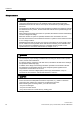
Function modules 7.6 Cooling system 7.6 Cooling system 7.6.1 "Cooling system" function module Features ● Control and monitoring functions of a cooling unit ● Automatically activated when using water-cooled power units ● Evaluation of a leakage water sensor (p0266.4) ● Evaluation of a water flow sensor (p0266.5, p0260, p0263) ● Evaluation of a conductivity sensor (p0266.6, p0266.
Figure 7-6 234 5.$ RQ U 7 U U 6 2SHUDWLRQ ุ U 5.$ :DWHU IORZ UDWH 2. U 5.$ VZLWFKHG RQ U 5.$ VZLWFKHG RQ U S 7 7 S ุ ุ 7 S U 6 )DXOW 1R 5.$ FRQGXFWLYLW\ IDXOW U S 7 5.$ 1R OHDNDJH ZDWHU U 5.$ VZLWFKHG RQ U 1R 5.$ IDXOW U U 5.$ :DWHU IORZ UDWH 2. 5.$ 1R OHDNDJH ZDWHU U ุ 1R 5.$ IDXOW U 5.
Function modules 7.7 Extended torque control (kT estimator, Servo) Function diagrams (see SINAMICS S List Manual) ● 9794 Cooling unit, control and feedback signals ● 9795 Cooling unit sequence control Overview of key parameters (see SINAMICS S List Manual) ● r0046.29 Missing enable signals - cooling unit ready missing ● p0192.06 Power unit firmware properties - water cooling ● r0204.
Function modules 7.7 Extended torque control (kT estimator, Servo) Parameter r0108.1 indicates whether it has been activated. Description of the kT estimator The adaptation of the torque constants for synchronous motors is used to improve the absolute torque accuracy for the control (closed-loop) of synchronous motors. The magnetization of the permanent magnets varies as a result of production tolerances and temperature fluctuations and saturation effects.
Function modules 7.8 Closed-loop position control kT estimator: ● p1752 Motor model, changeover speed operation with encoder ● p1795 Motor model PEM kT adaptation smoothing time ● r1797 Motor model PEM kT adaptation correction value Compensation of the voltage emulation error of the drive converter: ● p1952 Voltage emulation error, final value ● p1953 Voltage emulation error, current offset 7.8 Closed-loop position control 7.8.
Function modules 7.8 Closed-loop position control 7.8.2.2 Description The position actual value conditioning implements the conditioning of the position actual value in a neutral position unit LU (LENGTH UNIT). To do this, the function block uses the encoder evaluation/motor control with the available encoder interfaces Gn_XIST1, Gn_XIST2, Gn_STW and Gn_ZSW. These just provide position information in encoder pulses and fine resolution (increments).
Function modules 7.8 Closed-loop position control Note The effective actual value resolution is obtained from the product of the encoder pulses (p0408) and the fine resolution (p0418) and a measuring gear that is possibly being used (p0402, p0432, p0433).
Function modules 7.8 Closed-loop position control interconnected with r2685 (EPOS correction value) and p2512 with r2684.7 (activate correction). This interconnection enables modulo offset by EPOS, for example. p2516 can be used to switch in position offset. Using EPOS, p2516 is automatically interconnected to r2667. Backlash compensation is implemented using this interconnection.
Function modules 7.8 Closed-loop position control Description The indexed position actual value acquisition permits e.g. length measurements on parts as well as the detection of axis positions by a higher-level controller (e.g. SIMATIC S7) in addition to the position control e.g. of a belt conveyor. Two more encoders can be operated in parallel with the encoders for actual value preprocessing and position control in order to collect actual values and measured data.
Function modules 7.8 Closed-loop position control parameters p2504 and p2505. Position tracking can be activated with rotary axes (modulo) and linear axes. For linear axes, the virtual multiturn resolution (p2721) is preset with p0421 and extended by 6 bits for multiturn information (max. overflows 31 positive/negative) Position tracking for the load gearing can only be activated once for each motor data set MDS. The load position actual value in r2723 (must be requested via GnSTW.
Function modules 7.8 Closed-loop position control ([WHQGHG SRVLWLRQ DUHD WKURXJK YLUWXDO PXOWLWXUQ LQWHUQDOO\ PDSSHG WR (26 DUHD 3RVLWLRQ DEVROXWH HQFRGHU (QFRGHU UHYROXWLRQV Figure 7-10 U Position tracking (p2721 = 24) In this example, this means: Without position tracking, the position for +/- 4 encoder revolutions about r2521 = 0 LU can be reproduced.
Function modules 7.8 Closed-loop position control Virtual multiturn encoder (p2721) With a rotary absolute encoder (p0404.1 = 1) with activated position tracking (p2720.0 = 1), p2721 can be used to enter a virtual multiturn resolution. This enables you to generate a virtual multiturn encoder value (r2723) from a singleturn encoder. It must be possible to display the virtual encoder range via r2723.
Function modules 7.8 Closed-loop position control The current configuration can be checked in parameter r0108. The "load gearbox position tracking" function can be configured in the commissioning wizard via the "Mechanical system" dialog, as well as in the project navigator under "Technology" -> "Position control" via the "Mechanical system" dialog. 7.8.2.
Function modules 7.8 Closed-loop position control 7.8.3 Position controller Features ● Symmetrization (p2535, p2536) ● Limiting (p2540, p2541) ● Pre-control (p2534) ● Adaptation (p2537, p2538) Note We only recommend that experts use the position controller functions without using the basic positioner. Description The position controller is a PI controller. The P gain can be adapted using the product of connector input p2537 (position controller adaptation) and parameter p2538 (Kp).
Function modules 7.8 Closed-loop position control 7.8.4 Monitoring functions Features ● Standstill monitoring (p2542, p2543) ● Positioning monitoring (p2544, p2545) ● Dynamic following error monitoring (p2546, r2563) ● Cam controllers (p2547, p2548, p2683.8, p2683.
Function modules 7.
Function modules 7.8 Closed-loop position control ● p2546 LR dynamic following error monitoring tolerance ● p2547 LR cam switching position 1 ● p2548 LR cam switching position 2 ● p2551 BI: LR setpoint message present ● p2554 BI: LR travel command message active ● r2563 CO: LR latest following error ● r2683.8 Actual position value <= cam switching position 1 ● r2683.9 Actual position value <= cam switching position 2 ● r2684 CO/BO: EPOS status word 2 7.8.
Function modules 7.8 Closed-loop position control The alarm is also generated if, during an activated function (reference mark search or measuring probe evaluation), a fault is signaled using the encoder status word. If the "position control" function module is selected, these parameters (p2508 to p2511) are preassigned with "0".
Function modules 7.9 Basic positioner position controller monitoring functions respond. To prevent this from happening, the position controller must be disabled (p2550 = 0) and switch to tracking mode (p2655 = 1, for control using PROFIdrive telegram 110 PosSTW.0 = 1). In this way, the monitoring functions are switched off and the position setpoint is tracked.
Function modules 7.
Function modules 7.9 Basic positioner 7.9.1 Mechanical system Features ● Backlash compensation (p2583) ● Modulo offset (p2577) Description %DFNODVK S Figure 7-14 Backlash compensation When mechanical force is transferred between a machine part and its drive, generally backlash occurs. If the mechanical system was to be adjusted/designed so that there was absolutely no play, this would result in high wear. Thus, backlash (play) can occur between the machine component and the encoder.
Function modules 7.9 Basic positioner Table 7-4 p2604 0 1 The compensation value is switched in as a function of p2604 Traversing direction Switch in compensation value positive none negative immediately positive immediately negative none 0RGXOR UDQJH S 'H DFWLYDWHG 0RGXOR FRUUHFWLRQ DFWLYDWLRQ 3RVLWLRQ VHWSRLQW U S Figure 7-15 Modulo offset A modulo axis has an unrestricted traversing range.
Function modules 7.9 Basic positioner With position tracking it is recommended to change p0412 or p2721.
Function modules 7.9 Basic positioner The drive is limited to this velocity if a higher velocity is specified or programmed via the override (p2646) for the reference point approach or is programmed in the traversing block. Parameter p2571 (maximum velocity) defines the maximum traversing velocity in units 1000 LU/min. If the maximum velocity is changed, then this limits the velocity of a traversing task that is presently being executed.
Function modules 7.9 Basic positioner ● The modulo correction is not active (p2577 = "0") The connector inputs are, in the factory setting, linked to the connector output p2580 (software limit switch minus) and p2581 (software limit switch plus). Stop cam A traversing range can, on one hand, be limited per software using the software limit switches and on the other hand, the traversing range can be limited per hardware. In this case, the functionality of the stop cam (hardware limit switch) is used.
Function modules 7.9 Basic positioner 9HORFLW\ Figure 7-17 $FFHOHUDWLRQ 7LPH 9HORFLW\ P V $FFHOHUDWLRQ >P Vt@ Activated jerk limitation The maximum inclination (rk) can be set in parameter p2574 ("Jerk limitation") in the unit LU/s3 for both acceleration and braking. The resolution is 1000 LU/s3. To activate limiting permanently, set parameter p2575 ("Active jerk limitation") to 1.
Function modules 7.9 Basic positioner ● p2581 CO: EPOS software limit switch, plus ● p2582 BI: EPOS software limit switch activation ● r2683 CO/BO: EPOS status word 1 STOP cam ● p2568 BI: EPOS STOP cam activation ● p2569 BI: EPOS STOP cam, minus ● p2570 BI: EPOS STOP cam, plus ● r2684 CO/BO: EPOS status word 2 7.9.
Function modules 7.9 Basic positioner ● Flying referencing (passive (p2597 = 1)) ● Absolute encoder – Absolute encoder adjustment – Flying referencing (passive (p2597 = 1)) A connector input is provided for all referencing types to input the reference point coordinate; this allows, e.g. the change/input via the higher-level control. However, to permanently enter the reference point coordinate, a setting parameter for this quantity is also required.
Function modules 7.9 Basic positioner CAUTION During adjustment with the rotary absolute encoder, a range is aligned symmetrically around the zero point with half the encoder range within which the position is restored after switch off/on. If position tracking is deactivated (2720.0 = 0), only one encoder overflow is permitted to occur in this range (further details are given in chapter Position controller -> Actual position value conditioning).
Function modules 7.
Function modules 7.9 Basic positioner reversed. The reversing cams are low active. If both reversing cams are active (p2613 = "0" and p2614 = "0"), the drive remains stationary. As soon as the reference cam is found, then synchronization to the reference zero mark is immediately started (refer to step 2). If the axis leaves its start position and travels the distance defined in parameter p2606 (max.
Function modules 7.9 Basic positioner Note In this case the direction of approach to the reference zero mark is the opposite to the axes with reference cams! External zero mark present (p0495 ≠ 0), no reference cam (p2607 = 0): Synchronization to an external zero mark begins as soon as the signal at binector input p2595 (start homing) is detected.
Function modules 7.9 Basic positioner When "flying referencing" during incremental positioning (relative) you can select whether the offset value is to be taken into account for the travel path or not (p2603). The "flying referencing" is activated by a 0/1 edge at binector input p2595 (start referencing). The signal in binector input p2595 (start homing) must be set during the entire referencing process otherwise the process is aborted. Status bit r2684.
Function modules 7.9 Basic positioner Instructions for switching data sets Using drive data set switching (DDS), motor data sets (p0186) and encoder data sets (p0187 to p0189) can be switched. The following table shows when the reference bit (r2684.11) or the status of the adjustment with absolute encoders (p2507) is reset. In the following cases, when a DDS switch takes place, the current actual position value becomes invalid (p2521 = 0) and the reference point (r2684.11 = 0) is reset.
Function modules 7.9 Basic positioner 6 2 EDS5 EDS6 EDS7 encoder_1 zzz disabled 7 3 EDS0 EDS1 EDS2 encoder_1 xxx disabled reference bit 3) is reset. Operation: Error message is generated. Position actual value preprocessing is newly initiated 1) and reference bit 3) is reset.
Function modules 7.9 Basic positioner ● An external block change p2632 "External block change" is triggered. Traversing blocks are parameterized using parameter sets that have a fixed structure: ● Traversing block number (p2616[0...63]) Every traversing block must be assigned a traversing block number (in STARTER "No."). The traversing blocks are executed in the sequence of the traversing block numbers.
Function modules 7.9 Basic positioner the next task at any time during the traveling phase. If "External block change" is not triggered, the axis remains in the parameterized target position until the signal is issued. The difference here is that with CONTINUE_EXTERNAL, a flying changeover is carried out at the braking point if "External block change" has not been triggered, while here the drive waits for the signal in the target position.
Function modules 7.9 Basic positioner next interpolation clock cycle. CONTINUE_EXTERNAL_ALARM causes a message to be output immediately. FIXED STOP The FIXED STOP task triggers a traversing movement with reduced torque to fixed stop.
Function modules 7.9 Basic positioner A precise stop is always carried out here regardless of the parameterized continuation condition of the task preceding the JERK task. The following parameters are relevant: ● p2616[x] Block number ● p2622[x] Task parameter = 0 or 1 All continuation conditions are possible. WAITING The WAIT order can be used to set a waiting period, which should expire before the following order is processed.
Function modules 7.9 Basic positioner SET_O, RESET_O The tasks SET_O and RESET_O allow up to two binary signals (output 1 or 2) to be simultaneously set or reset. The number of the output (1 or 2) is specified bit-coded in the task parameter. The following parameters are relevant: ● p2616[x] Block number ● p2622[x] Task parameter = bit-coded output: 0x1: Output 1 0x2: Output 2 0x3: Output 1 + 2 Possible continuation conditions are END, CONTINUE_ON-THE-FLY and CONTINUE_WITH_STOP, and CONTINUE_EXTERNAL_WAIT.
Function modules 7.9 Basic positioner In positioning mode, traversing to a fixed stop is started when a traversing block is processed with the FIXED STOP command. In this traversing block, in addition to the specification of the dynamic parameterized position, speed, acceleration override and delay override, the required clamping torque can be specified as task parameter p2622. From the start position onwards, the target position is approached with the parameterized speed.
Function modules 7.9 Basic positioner Note If the drive is in fixed stop, it can be referenced using the control signal "set reference point." If the axis leaves the position that it had at detection of the fixed stop by more than the selected monitoring window for the fixed stop p2635, then the status bit r2683.12 is reset. At the same time, the speed setpoint is set to zero, and the alarm F07484 "fixed stop outside of the monitoring window" is triggered with the reaction OFF3 (quick stop).
Function modules 7.9 Basic positioner 7.9.5.5 Vertical axes Note In servo mode, with suspended axes, a torque limit offset (p1532) can be entered (see chapter: Servo Control -> Suspended axes). With asymmetrical torque limits p1522 and p1523, when traversing to fixed stop, the fixed weight is taken into account in the parameters r2686 and r2687.
Function modules 7.9 Basic positioner 7.9.
Function modules 7.9 Basic positioner Note Continuous acceptance p2649 = 1 can only be set with free telegram configuration p0922 = 999. No relative positioning is allowed with continuous acceptance. The direction of positioning can be specified using p2651 (positive direction specification) and p2652 (negative direction specification). If both inputs have the same status, the shortest distance is traveled during absolute positioning (p2648 = "1") of modulo axes (p2577 = "1").
Function modules 7.9 Basic positioner ● xx2x = ABS_POS -> p2648, p2651 ● xx3x = ABS_NEG -> p2648, p2652 Intermediate stop and canceling traversing block The intermediate stop is activated by a 0 signal at p2640. After activation, the system brakes with the parameterized deceleration value (p2620 or p2645). The current traversing task can be canceled by a 0 signal at p2641. After activation, the system brakes with the maximum deceleration (p2573).
Function modules 7.9 Basic positioner 7.9.7 Jog Features ● Jog signals (p2589, p2590) ● Velocity (p2585, p2586) ● Incremental (p2587, p2588, p2591) Description Using parameter p2591 it is possible to change over between jog incremental and jog velocity. The traversing distances p2587 and p2588 and velocities p2585 and p2586 are entered using the jog signals p2589 and p2590. The traversing distances are only effective for a "1" signal at p2591 (jog, incremental).
Function modules 7.9 Basic positioner Function diagrams (see SINAMICS S List Manual) ● 3610 EPOS - jog mode Overview of key parameters (see SINAMICS S List Manual) ● p2585 EPOS jog 1 setpoint velocity ● p2586 EPOS jog 2 setpoint velocity ● p2587 EPOS jog 1 traversing distance ● p2588 EPOS jog 2 traversing distance ● p2589 BI: EPOS jog 1 signal source ● p2590 BI: EPOS jog 2 signal source ● p2591 BI: EPOS jog incremental 7.9.
Function modules 7.9 Basic positioner Stop cam minus active (r2684.13) Stop cam plus active (r2684.14) These status signals indicate that the stop cam minus p2569 or stop cam plus p2570 were reached or passed. The signals are reset if the cams are left in a directly opposing the approach direction. Axis moves forwards (r2683.4) Axis moves backwards (r2683.5) Axis accelerates (r2684.4) Drive decelerates (r2684.5) Drive stationary (zero speed) (r2199.0) These signals display the current motion status.
Function modules 7.10 DCC axial winder ● Signal level 1 at binector input p2551 "signal setpoint static". Reference point set (r2684.11) The signal is set as soon as referencing has been successfully completed. It is deleted as soon as no reference is there or at the start of the reference point approach. Acknowledgement, traversing block activated (r2684.
Function modules 7.10 DCC axial winder ● Adaptation of tension controller and speed controller gain based on diameter or inertia ● Diameter-based winding tightness diagram ● Diameter calculation ● Acceleration-based torque pre-control ● Flexible sensor evaluation (e.g. dancer roll, load cell) Note Documentation for a standard application for the DCC axial winder is available on demand from your responsible SIEMENS distribution partner.
Function modules 7.
Function modules 7.10 DCC axial winder The function diagram below shows the calculation flow for VECTOR control [FP 6031]: dn/dt 0BSUH FRQWUROB > @ $FFHOHUDWLRQ FDOFXODWLRQ 9HFWRU > @ DBEHIRUH VFDOLQJ 3 p1497 1 r1493 0RW 0BLQHUWLD >NJP @ S DBEHIRUH VFDOLQJ 3 0RW 0RP,QHUW 5DWLR > @ S Figure 7-23 Torque pre-control for VECTOR control Parameters for the function diagrams for torque pre-control p0341[0...
Function modules 7.10 DCC axial winder p1497[0...n] CI: Moment of inertia, scaling / M_mom inert scal Scaling factor of the static moment of inertia for the calculation of the current total moment of inertia (r1493 + portion of the moment of inertia of the winding product calculated by the INCO block). p1498[0...
Function modules 7.10 DCC axial winder A variable torque limit is effective (fixed torque limit + scaling). 0 signal from BI: p1551: The fixed torque limit is effective. p1552[0...n] Torque limit upper scaling without offset / M_max up offs scal Sets the signal source for the scaling of the upper torque limit to limit the speed controller output without considering current and power limits. A possible source is the torque preset from the DCC diagram. p1554[0...
Function modules 7.11 Parallel connection of chassis power units (vector) 7.11 Parallel connection of chassis power units (vector) 7.11.1 Features SINAMICS supports the parallel connection of power units on the motor and infeed side to extend the power spectrum of the SINAMICS.
Function modules 7.11 Parallel connection of chassis power units (vector) ● ... ● p7322 Parallel circuit configuration, VSM line filter capacitance, phaseW 7.11.3 Description Switching power units in parallel is a simple method of extending the power spectrum of drives beyond the power of the individual power units. 7.11.
Function modules 7.11 Parallel connection of chassis power units (vector) Parallel connection of two Active Line Modules and two Motor Modules on a motor with a single winding system 8 9 : &RQWURO 8QLW '5,9( &/L4 9ROWDJH 6HQVLQJ 0RGXOH $FWLYH ,QWHUIDFH 0RGXOH $FWLYH ,QWHUIDFH 0RGXOH 9ROWDJH 6HQVLQJ 0RGXOH $FWLYH /LQH 0RGXOH $FWLYH /LQH 0RGXOH 0RWRU 0RGXOH 0RWRU 0RGXOH 0 Figure 7-26 7.11.
8 Monitoring and protective functions 8.1 Power unit protection, general Description SINAMICS power units offer comprehensive functions for protecting power components. Table 8-1 General protection for power units Protection against: Overcurrent1) Precautions Monitoring with two thresholds: • First threshold exceeded Responses A30031, A30032, A30033 Current limiting of a phase has responded. The pulsing in the phase involved is inhibited.
Monitoring and protective functions 8.2 Thermal monitoring and overload responses 8.2 Thermal monitoring and overload responses Description The priority of thermal monitoring for power unit is to identify critical situations. If alarm thresholds are exceeded, the user can set parameterizable response options that enable continued operation (e.g. with reduced power) and prevent immediate shutdown.
Monitoring and protective functions 8.3 Block protection Reducing the output frequency has the effect of significantly reducing the converter output current which, in turn, reduces losses in the power unit. ● No reduction (p0290 = 1) You should choose this option if it is neither possible to reduce the pulse frequency nor reduce the output current.
Monitoring and protective functions 8.
Monitoring and protective functions 8.
Monitoring and protective functions 8.5 Thermal motor protection Temperature measurement via KTY The device is connected to terminals X522:7 (anode) and X522:8 (cathode) at the customer terminal block (TM31) in the diode conducting direction. The measured temperature is limited to between -48 °C and +248°C and is made available for further evaluation.
Monitoring and protective functions 8.
Safety Integrated basic functions 9.1 9 General information Note This manual describes the Safety Integrated Basic Functions. The Safety Integrated Extended Functions are described in the following documentation: Reference: /FHS/ SINAMICS S120 Function Manual Safety Integrated. 9.1.1 Explanations, standards, and terminology Safety Integrated The "Safety Integrated" functions, which have been prototype tested, provide highly-effective application-oriented protection for personnel and machinery.
Safety Integrated basic functions 9.
Safety Integrated basic functions 9.1 General information Switch-off signal paths Two independent switch-off signal paths are available. All switch-off signal paths are low active, thereby ensuring that the system is always switched to a safe state if a component fails or in the event of an open circuit. If a fault is discovered in the switch-off signal paths, the "Safe Torque Off" function is activated and a system restart inhibited.
Safety Integrated basic functions 9.1 General information – Safe torque off (STO) STO is a safety function that prevents the drive from restarting unexpectedly, in accordance with EN 60204-1, Section 5.4. Note When a drive object that has Safety Integrated functions released is switched to "Parking" mode, the Safety Integrated software responds by activating STOP without generating a separate message. – Safe Stop 1 (SS1, time controlled) Safe Stop 1 is based on the "Safe Torque Off" function.
Safety Integrated basic functions 9.1 General information ● SIMOTION D4x5: FW version from V4.1.1 (SINAMICS S120 with FW version from V2.5 SP1 integrated) ● Safe actual value acquisition (see chapter "Safe actual value acquisition") ● An activated speed controller in the drive ● Overview of hardware components that support the Extended Functions: – Control Unit CU310 from order no.: 6SL3040-0LA00-0AA1/6SL3040-0LA01-0AA1 – Control Unit CU320 from order no.: 6SL3040-...
Safety Integrated basic functions 9.1 General information Checking the checksum For each monitoring channel, the safety parameters include one parameter for the actual checksum for the safety parameters that have undergone a checksum check. During commissioning, the actual checksum must be transferred to the corresponding parameter for the specified checksum. This can be done for all checksums of a drive object at the same time with parameter p9701.
Safety Integrated basic functions 9.1 General information Password The safety password protects the safety parameters against unauthorized write access. In commissioning mode for Safety Integrated (p0010 = 95), you cannot change safety parameters until you have entered the valid safety password in p9761 for the drives or p10061 for the TM54F.
Safety Integrated basic functions 9.1 General information ● p10062 SI password new TM54F ● p10063 SI password acknowledgement TM54F 9.1.4 Forced dormant error detection Forced dormant error detection or test for the switch-off signal paths Forced dormant error detection for the switch-off signal paths is used for detecting errors in the software/hardware of the two monitoring channels as quickly as possible and is carried out automatically when the "Safe Torque Off" function is activated/deactivated.
Safety Integrated basic functions 9.2 Safety instructions 9.2 Safety instructions Safety instructions WARNING After hardware and/or software components have been modified or replaced, it is only permissible for the system to run up and the drives to be activated with the protective devices closed. Personnel may not be in the hazardous area. Depending on the change made or what has been replaced, it may be necessary to carry out a partial or complete acceptance test (see chapter "Acceptance test").
Safety Integrated basic functions 9.3 Safe Torque Off (STO) CAUTION The "automatic restart" function may not be used together with the safety functions STO/SBC and SS1. The reason for this is that EN 60204 Part 1 (1998) in chapter 9.2.5.4.2 does not permit this (merely de-selecting a safety shutdown function must not cause the machine to restart). NOTICE Components cannot be deactivated via p0105, for example, with activated Safety functions. 9.
Safety Integrated basic functions 9.3 Safe Torque Off (STO) CAUTION If two power transistors in the power unit (one in the upper and one offset in the lower inverter bridge) fail at the same time, this can cause a momentary movement. The maximum movement can be: Synchronous rotary motors: max. movement = 180° / no. of pole pairs Synchronous linear motors: max. movement = pole width ● The status of the "Safe Torque Off" function is displayed using parameters.
Safety Integrated basic functions 9.3 Safe Torque Off (STO) Restart after the "Safe Torque Off" function has been selected 1. Deselect the function in each monitoring channel via the input terminals. 2. Issue drive enable signals. 3. Revoke the closing lockout and switch the drive back on. – 1/0 edge at input signal "ON/OFF1" (cancel power-on inhibit) – 0/1 edge at input signal "ON/OFF1" (switch on drive) 4. Run the drives again.
Safety Integrated basic functions 9.4 Safe Stop 1 (SS1, time controlled) Parameter overview (see List Manual) ● p0799 CU inputs/outputs sampling times ● r9780 SI monitoring clock cycle (Control Unit) ● r9880 SI monitoring clock cycle (Motor Module) 9.4 Safe Stop 1 (SS1, time controlled) General description The "Safe Stop 1" function can be used to stop the drive in accordance with EN 60204-1, stop category 1.
Safety Integrated basic functions 9.5 Safe Brake Control (SBC) Status for "Safe Stop 1" The status of the "Safe Stop 1" function is displayed using the following parameters: ● r9772 CO/BO: SI status (Control Unit) ● r9773 CO/BO: SI status (Control Unit + Motor Module) ● r9774 CO/BO: SI status (Safe Torque Off group) ● r9872 CO/BO: SI status (Motor Module) Alternatively, the status of the functions can be displayed using the configurable messages N01621 and N30621 (configured using p2118 and p2119).
Safety Integrated basic functions 9.5 Safe Brake Control (SBC) WARNING "Safe Brake Control" does not detect faults in the brake itself, such as brake winding shortcircuit, worn brakes, etc. If a cable breaks, this is only recognized by the "Safe Brake Control" function when the status changes, i.e. when the brake is applied/released. Functional features of "Safe Brake Control" (SBC) ● When "Safe Torque Off" is selected or when safety monitors are triggered, "SBC" is performed with safe pulse cancellation.
Safety Integrated basic functions 9.
Safety Integrated basic functions 9.6 Control via terminals on the Control Unit and the power unit Parameter overview (see SINAMICS S List Manual) ● p0799 CU inputs/outputs sampling times ● r9780 SI monitoring clock cycle (Control Unit) ● r9880 SI monitoring clock cycle (Motor Module) 9.
Safety Integrated basic functions 9.6 Control via terminals on the Control Unit and the power unit Terminals for STO, SS1 (time-controlled), SBC The functions are separately selected/deselected for each drive using two terminals. ● 1. Switch-off signal path (CU310/CU320) The desired input terminal is selected via BICO interconnection (BI: p9620[0]). ● 2. Switch-off signal path (Motor Module/Power Module/CUA31) The input terminal is the "EP" ("Enable Pulses") terminal.
Safety Integrated basic functions 9.6 Control via terminals on the Control Unit and the power unit The assignment is checked during the test for the switch-off signal paths, The operator selects "Safe Torque Off" for each group. The check is drive-specific. Example: Terminal groups It must be possible to select/deselect "Safe Torque Off" separately for group 1 (drive 1 and 2) and group 2 (drive 3 and 4).
Safety Integrated basic functions 9.7 Commissioning the "STO", "SBC" and "SS1" functions "Simultaneously" means: The changeover must be complete in both monitoring channels within the parameterized tolerance time. ● p9650 SI tolerance time F-DI changeover (Control Unit) ● p9850 SI tolerance time F-DI changeover (Motor Module) If the "Safe Torque Off" function is not selected/deselected within the tolerance time, this is detected by the crosswise comparison, and fault F01611 or F30611 (STOP F) is output.
Safety Integrated basic functions 9.7 Commissioning the "STO", "SBC" and "SS1" functions Prerequisites for commissioning the safety functions 1. Commissioning of the drives must be complete. 2. Non-safe pulse disable must be present (e.g. via OFF1 = "0" or OFF2 = "0") If the motor holding brake is connected and parameterized, the holding brake is applied. 3. The terminals for "Safe torque off" must be wired. 4.
Safety Integrated basic functions 9.7 Commissioning the "STO", "SBC" and "SS1" functions 9.7.2 Procedure for commissioning "STO", "SBC" and "SS1" To commission the "STO", "SBC" and "SS1" functions, carry out the following steps: Table 9-4 No. 1 Commissioning the "STO", "SBC" and "SS1" functions Parameter p0010 = 95 Description/comments Safety Integrated: set commissioning mode.
Safety Integrated basic functions 9.7 Commissioning the "STO", "SBC" and "SS1" functions No. Parameter Description/comments Enable "Safe Stop 1" function. 5 p9652 > 0 Enable "SS1" on the Control Unit p9852 > 0 Enable "SS1" on the Motor Module • The parameters are not changed until safety commissioning mode has been exited (i.e. when p0010 ≠ 95 is set). • Both parameters are included in the crosswise data comparison and must, therefore, be identical.
Safety Integrated basic functions 9.7 Commissioning the "STO", "SBC" and "SS1" functions No. Parameter Set transition period from STOP F to STOP A. 8 9 Description/comments p9658 = "Value" Transitional period from STOP F to STOP A on Control Unit p9858 = "Value" Transitional period from STOP F to STOP A on Motor Module • The parameters are not changed until safety commissioning mode has been exited (i.e. when p0010 ≠ 95 is set).
Safety Integrated basic functions 9.7 Commissioning the "STO", "SBC" and "SS1" functions No.
Safety Integrated basic functions 9.7 Commissioning the "STO", "SBC" and "SS1" functions Stop response Action Effect Triggered ... STOP A is identical to stop Category 0 to EN 60204-1. With STOP A, the motor is switched directly to zero torque via the "Safe torque off (STO)" function. A motor at standstill cannot be started again accidentally. A moving motor coasts to standstill. This can be prevented by using external braking mechanisms (e.g. armature short-circuiting, holding or operational brake).
Safety Integrated basic functions 9.8 Acceptance test and certificate Description of faults and alarms Note The faults and alarms for SINAMICS Safety Integrated are described in the following documentation: References: /LH1/ SINAMICS S List Manual 9.8 Acceptance test and certificate 9.8.1 General information about acceptance Acceptance test The machine manufacturer must carry out an acceptance test for the activated Safety Integrated functions (SI functions) on the machine.
Safety Integrated basic functions 9.8 Acceptance test and certificate Scope of a complete acceptance test Documentation Machine documentation (including the SI functions) 1. Machine description and overview diagram 2. SI functions for each drive 3. Description of safety equipment Functional test Check the individual SI functions used 1. "Safe torque off" function, part 1 2. "Safe torque off" function, part 2 3. "Safe Stop 1" function 4.
Safety Integrated basic functions 9.
Safety Integrated basic functions 9.8 Acceptance test and certificate Table 9-8 SI functions for each drive Drive number Table 9-9 SI function Description of safety equipment Examples: Wiring of STO terminals (protective door, emergency OFF), grouping of STO terminals, holding brake for vertical axis, etc.
Safety Integrated basic functions 9.8 Acceptance test and certificate 9.8.3 Acceptance test for Safe Torque Off (STO) "Safe Torque Off" (STO) function This test comprises the following steps: Table 9-10 "Safe Torque Off" (STO) function No. 1. Description Status Initial state Drive in "Ready" status (p0010 = 0) STO function enabled (p9601.0 = 1, p9801.0 = 1) No safety faults and alarms (r0945, r2122, r2132) r9772.0 = r9772.1 = 0 (STO de-selected and inactive – CU) r9872.0 = r9872.
Safety Integrated basic functions 9.8 Acceptance test and certificate No. Description Status The following is tested: • Correct DRIVE-CLiQ wiring between Control Unit and Motor Modules • Correct assignment of drive No.
Safety Integrated basic functions 9.8 Acceptance test and certificate No. Description • r9773.0 = r9773.1 = 0 (STO de-selected and inactive – drive) • r9773.2 = 1 (SS1 active – drive) Status STO is initiated after the SS1 delay time expires (p9652, p9852). • No safety faults and alarms (r0945, r2122, r2132) • r9722.0 = r9772.1 = 1 (STO selected and active – CU) • r9872.0 = r9872.1 = 1 (STO selected and active – MM) • r9772.2 = r9872.2 = 0 (SS1 inactive – CU and MM) • r9773.0 = r9773.
Safety Integrated basic functions 9.8 Acceptance test and certificate No. Description • • 2. Status Vertical axis: Mechanical brake is applied No vertical axis: Mechanical brake is released • No safety faults or alarms (r0945, r2122) • r9772.0 = r9772.1 = 0 (STO de-selected and inactive – CU) • r9872.0 = r9872.1 = 0 (STO de-selected and inactive – MM) • r9773.0 = r9773.1 = 0 (STO de-selected and inactive – drive) • r9772.4 = r9872.
Safety Integrated basic functions 9.8 Acceptance test and certificate 9.8.6 Completion of certificate SI parameters Specified values checked? Yes No Control Unit Motor Module Checksums Drive Checksum (8 hex) Name Drive number Control Unit (p9798) Motor Module (p9898) Data backup Storage medium Type Designation Storage location Date Parameter PLC program Circuit diagrams Countersignatures Commissioning engineer This confirms that the tests and checks have been carried out properly.
Safety Integrated basic functions 9.9 Application examples Machine manufacturer This confirms that the parameters recorded above are correct. Date Name Company/dept. Signature 9.9 Application examples 9.9.1 Safe Stop 1 (SS1, time-controlled) when protective door is locked, emergency stop switch-off 3 0DLQ FLUFXLW EUHDNHU 4 (PHUJ VWRS /HDGLQJ FORVLQJ FRQWDFW W ! PV 6 'LJLWDO RXWSXWV $ < < < < < '2 '2 '2 '2 '2 7.
Safety Integrated basic functions 9.
Safety Integrated basic functions 9.9 Application examples ● The "Safe Torque Off" safety function, which is integrated in the drive, complies with category 3 to EN 954-1 and SIL 2 to IEC 61508. The non-safe message "Safe Torque Off active" is sufficient. ● Safety combinations for emergency stop and protective door monitoring comply with category 4 (instantaneous enable circuits). ● The electric circuits for emergency stop and protective door monitoring are monitored for cross-circuits on two channels.
Safety Integrated basic functions 9.9 Application examples Behavior when the protective door is opened To issue a request to open the protective door, press the S2 button ("OFF"). The drive is brought to a standstill in accordance with stop category 1 of EN 60204-1. ● Resetting the PLC output DO 2 will trigger an SS1 at terminal X122.2 on the CU (DI 1) and at the EP terminals of the Motor Modules. The drives are immediately braked via the speed ramp (p1135). The speed ramp is not monitored for SS1.
Safety Integrated basic functions 9.10 Overview of parameters and function diagrams 9.10 Overview of parameters and function diagrams Parameter overview (see SINAMICS S List Manual) Table 9-13 Parameters for Safety Integrated No. of Control Unit (CU) No.
Safety Integrated basic functions 9.
10 Communication PROFIBUS DP/PROFINET IO 10.1 Communications according to PROFIdrive 10.1.1 General information about PROFIdrive for SINAMICS General information PROFIdrive V4.1 is the PROFIBUS and PROFINET profile for drive technology with a wide range of applications in production and process automation systems. PROFIdrive is independent of the bus system used (PROFIBUS, PROFINET).
Communication PROFIBUS DP/PROFINET IO 10.1 Communications according to PROFIdrive Examples: Programming devices, human machine interfaces ● Drive Unit (PROFIBUS: Slave, PROFINET IO: IO Device) The SINAMICS drive unit is with reference to PROFIdrive, a Drive Unit. Interface IF1 and IF2 The Control Unit can communicate via two different interfaces (IF1 and IF2).
Communication PROFIBUS DP/PROFINET IO 10.1 Communications according to PROFIdrive Application class 1 (Standard drive) In the most basic case, the drive is controlled via a speed setpoint by means of PROFIBUS/PROFINET. In this case, speed control is fully handled in the drive controller. Typical application examples are basic frequency converters. Pump and fan control.
Communication PROFIBUS DP/PROFINET IO 10.1 Communications according to PROFIdrive Application class 2 (Standard drive with technology function) The total process is subdivided into a number of small subprocesses and distributed among the drives. This means that the automation functions no longer reside exclusively in the central automation device but are also distributed in the drive controllers. Of course, this distribution assumes that communication is possible in every direction, i.e.
Communication PROFIBUS DP/PROFINET IO 10.1 Communications according to PROFIdrive Application class 3 (positioning drive) In addition to the drive control, the drive also includes a positioning control, so that the drive operates as a self-contained single-axis positioning drive while the higher-level technological processes are executed on the controller. Positioning requests are transmitted to the drive controller via PROFIBUS/PROFINET and launched.
Communication PROFIBUS DP/PROFINET IO 10.1 Communications according to PROFIdrive Application class 4 (central motion control) This application class defines a speed setpoint interface with execution of the speed control on the drive and of the positioning control in the controller, such as is required for robotics and machine tool applications with coordinated motions on multiple drives. Motion control is primarily implemented by means of a central numerical controller (CNC).
Communication PROFIBUS DP/PROFINET IO 10.
Communication PROFIBUS DP/PROFINET IO 10.1 Communications according to PROFIdrive From the perspective of the drive unit, the received process data comprises the receive words and the process data to be sent the send words. The receive and send words comprise the following elements: ● Receive words: Control words or setpoints ● Send words: Status words or actual values What telegrams are available? 1. Standard telegrams The standard telegrams are structured in accordance with the PROFIdrive Profile.
Communication PROFIBUS DP/PROFINET IO 10.1 Communications according to PROFIdrive 3. Free telegrams (p0922 = 999) The send and receive telegrams can be configured as required by using BICO technology to interconnect the send and receive process data. SERVO, TM41 VECTOR CU_S A_INF, B_INF, S_INF, TB30, TM31, TM15DI/DO Receive process data DWORD connector output r2060[0 ... 14] r2060[0 ... 30] - WORD connector output r2050[0 ... 15] r2050[0 ... 31] r2050[0 ...
Communication PROFIBUS DP/PROFINET IO 10.1 Communications according to PROFIdrive The telegram structure The parameter p0978 contains the sequence of DOs that use a cyclic PZD exchange. A zero delimits the DOs that do not exchange any PZDs. If the value 255 is written to p0978, the drive unit emulates an empty drive object that is visible to the PROFIdrive controller.
Communication PROFIBUS DP/PROFINET IO 10.1 Communications according to PROFIdrive 7HOHJUDP $SSO FODVV '6& '6& '6& 3=' 3=' 3=' 3=' 3=' 3=' 3=' 3=' 3=' 3=' 3=' 3=' 3=' 3=' 3=' 3=' 3=' 3=' 3=' &7: 67: &7: 67: &7: 67: &7: ( B;,67 &7: 67: &7: %/&.6(/ $&7%/&.
Communication PROFIBUS DP/PROFINET IO 10.1 Communications according to PROFIdrive Drive object Telegrams (p0922) TM31 No predefined telegram. TM41 3, 999 TB30 No predefined telegram. CU_S 390, 391, 392, 999 Depending on the drive object, the following maximum number of process data items can be transmitted for user-defined telegram structures: Drive object • A_INF Max.
Communication PROFIBUS DP/PROFINET IO 10.1 Communications according to PROFIdrive Function diagrams (see SINAMICS S List Manual) ● 2410 PROFIBUS address, diagnostic ● ... ● 2483 Send telegram, free interconnection via BICO (p0922 = 999) 10.1.3.2 Monitoring: telegram failure Description After a telegram failure and a monitoring time has elapsed (p2047), bit r2043.0 is set to "1" and alarm A01920 is output. Binector output r2043.0 can be used for an emergency stop, for example.
Communication PROFIBUS DP/PROFINET IO 10.1 Communications according to PROFIdrive drive objects and alarm A01920 and fault F01910 are output for VECTOR. When F01910 is output, an OFF3 is triggered for the drive. After a delay time (p2044) of two seconds has elapsed, fault F01910 is output on the infeed and triggers OFF2. 10.1.3.3 Description of control words and setpoints Note This chapter describes the assignment and meaning of the process data in SINAMICS interface mode (p2038 = 0).
Communication PROFIBUS DP/PROFINET IO 10.1 Communications according to PROFIdrive Abbreviation MDIAcc Name Pos MDI acceleration override Signal number Data type 1) 225 I16 Interconnection parameters p2644 MDIDec Pos MDI deceleration override 227 I16 p2645 MDIMode Pos MDI mode 229 U16 p2654 E_STW1 Control word for INFEED 320 U16 (bit serial)2) CU_STW Control word for Control Unit (CU) 500 U16 (bit serial) 1.
Communication PROFIBUS DP/PROFINET IO 10.1 Communications according to PROFIdrive Bit Meaning Comments BICO Note: The ramp-function generator cannot be frozen via p1141 in jog mode (r0046.31 = 1). 6 7 Enable speed setpoint Acknowledge fault 1 Enable setpoint 0 Inhibit setpoint Set ramp-function generator input to zero 0/1 Acknowledge fault 0 No effect BI: p1142 BI: p2103 Note: Faults are acknowledged at a 0/1 edge via BI: p2103 or BI: p2104 or BI: p2105.
Communication PROFIBUS DP/PROFINET IO 10.1 Communications according to PROFIdrive Bit 1 Meaning OFF2 Comments 1 No OFF2 Enable possible 0 OFF2 Immediate pulse cancellation and power-on inhibit BICO BI: p0844 Note: Control signal OFF2 is generated by ANDing BI: p0844 and BI: p0845. 2 OFF3 1 No OFF3 Enable possible 0 Emergency stop (OFF3) Braking with OFF3 ramp p1135, then pulse cancellation and power-on inhibit. BI: p0848 Note: Control signal OFF3 is generated by ANDing BI: p0848 and BI: p0849.
Communication PROFIBUS DP/PROFINET IO 10.
Communication PROFIBUS DP/PROFINET IO 10.1 Communications according to PROFIdrive Table 10-7 Description of E_CTW1 (control word for INFEED) Bit 0 1 Meaning ON/OFF1 OFF2 Comments 0/1 ON Pulse enable possible 0 OFF1 Reduce DC link voltage via ramp (p3566), pulse inhibit/line contactor open 1 No OFF2 Enable possible 0 OFF2 Immediate pulse cancellation and power-on inhibit BICO BI: p0840 BI: p0844 Note: Control signal OFF2 is generated by ANDing BI: p0844 and BI: p0845.
Communication PROFIBUS DP/PROFINET IO 10.1 Communications according to PROFIdrive Bit Meaning Comments BICO Note: This bit should not be set to "1" until the PROFIdrive has returned an appropriate status via STW1.9 = "1".. 11 Reserved - - - 12 Reserved - - - 13 Reserved - - - 14 Reserved - - - 15 Reserved - - - SATZANW (positioning mode, p0108.4 =1) See function diagram [2476] Table 10-8 Description of BLOCKSEL (positioning mode, p0108.
Communication PROFIBUS DP/PROFINET IO 10.1 Communications according to PROFIdrive Bit Meaning 4 Reserved 5 Jogging, incremental 6 ... 15 Comments Reserved BICO 0 The sensor for the fixed stop is inactive - - BI: 2591 1 Jogging incremental active 0 Jogging velocity active - - - Note: See also: SINAMICS S Function Manual, Function module "basic positioner" NSOLL_A (speed setpoint A (16-bit)) ● Speed setpoint with a 16-bit resolution with sign bit.
Communication PROFIBUS DP/PROFINET IO 10.1 Communications according to PROFIdrive The format of XERR is identical to the format of G1_XIST1. KPC (position controller gain factor) ) The position controller gain factor for dynamic servo control (DSC) is transmitted via this setpoint. Transmission format: KPC is transmitted in the unit 0.001 1/s Range of values: 0 to 4000.0 Special case: When KPC = 0, the "DSC" function is deactivated. Example: A2C2A hex ≐ 666666 dec ≐ KPC = 666.
Communication PROFIBUS DP/PROFINET IO 10.1 Communications according to PROFIdrive Over (pos velocity override) This process data defines the percentage for the velocity override. Normalization: 4000 hex (16384 dec) = 100 % Range of values: 0 ... 7FFF hex Values outside this range are interpreted as 0%. TORQUERED (torque reduction) ) This setpoint can be used to reduce the torque limit currently active on the drive.
Communication PROFIBUS DP/PROFINET IO 10.1 Communications according to PROFIdrive 10.1.3.4 Description of status words and actual values Description of status words and actual values Note This chapter describes the assignment and meaning of the process data in SINAMICS interface mode (p2038 = 0). The reference parameter is also specified for the relevant process data. The process data is generally normalized in accordance with parameters p2000 to r2004.
Communication PROFIBUS DP/PROFINET IO 10.
Communication PROFIBUS DP/PROFINET IO 10.1 Communications according to PROFIdrive Bit 3 4 5 6 7 8 9 10 Meaning Fault active Coasting active (OFF2) Fast stop active (OFF3) Power-on disable Alarm present Speed setpoint-actual value deviation within tolerance band Control requested f or n comparison value reached or exceeded Comments 1 Fault active The drive is faulty and, therefore, out of service.
Communication PROFIBUS DP/PROFINET IO 10.1 Communications according to PROFIdrive Bit 12 13 Meaning Holding brake open No motor overtemperature alarm Comments BICO BO: r0899.12 1 Holding brake open 0 Holding brake closed 1 Motor overtemperature alarm not active 0 Motor overtemperature alarm active BO: r2135.14 (inverted) BO: r2197.
Communication PROFIBUS DP/PROFINET IO 10.1 Communications according to PROFIdrive Bit 6 7 Meaning Power-on disable Alarm present Comments 1 Power-on disable A restart is only possible by means of OFF1 and then ON. 0 No power-up inhibit Power-up is possible. 1 Alarm present The drive is operational again. No acknowledgement necessary. BICO BO: r0899.6 BO: r2139.7 The active alarms are stored in the alarm buffer.
Communication PROFIBUS DP/PROFINET IO 10.1 Communications according to PROFIdrive Bit 4 5, 6 7 8 Meaning BICO DDS eff., bit 4 – Reserved – – – BO: r0896.0 Parking axis Travel to fixed endstop 9, 10 Reserved 11 Comments Data set changeover BO: r0051.4 1 Axis parking active 0 Axis parking not active 1 Travel to fixed endstop BO: r1406.8 0 No travel to fixed stop – – – BO: r0835.
Communication PROFIBUS DP/PROFINET IO 10.1 Communications according to PROFIdrive Bit Meaning Comments 1/0 Ramp-up starts. The start of the ramp-up procedure is detected as follows: • The speed setpoint changes, and • the defined tolerance bandwidth (p2164) is exited. 0 Ramp-function generator active • The ramp-up procedure is still active once the speed setpoint has been changed. 0/1 1 Torque utilization < p2194 BICO Ramp-up ends.
Communication PROFIBUS DP/PROFINET IO 10.1 Communications according to PROFIdrive Bit Meaning Comments BICO Note: The message is parameterized as follows: p2155 Threshold value p2140 Hysteresis Application: Speed monitoring. 4 5 6 Reserved Reserved No motor overtemperature alarm 1 – 0 - 1 – 0 – 1 No motor overtemperature alarm The temperature of the motor is within the permissible range.
Communication PROFIBUS DP/PROFINET IO 10.1 Communications according to PROFIdrive MSOLL_GLATT The torque setpoint smoothed with p0045 is displayed. AIST_GLATT Torque utilization smoothed with p0045 is displayed. E_DIGITAL MT_STW MT_n_ZS_F/MT_n_ZS_S CU_ZSW This process data is part of the central process data. IAIST_GLATT The actual current value smoothed with p0045 is displayed. MIST_GLATT The actual torque value smoothed with p0045 is displayed.
Communication PROFIBUS DP/PROFINET IO 10.1 Communications according to PROFIdrive Bit 1 Meaning Ready to run 2 Operation enabled 3 Fault active 4 No OFF2 active Comments 1 Ready to run DC link pre-charged, pulses inhibited 0 Not ready 1 Operation enabled Vdc = Vdc_setp 0 Operation inhibited 1 Fault active 0 No fault 1 No OFF2 active 0 OFF2 active BO: r0899.
Communication PROFIBUS DP/PROFINET IO 10.1 Communications according to PROFIdrive Bit 2 Meaning Setpoint static Comments BICO BO: r2683.2 1 Setpoint static 0 Setpoint not static 3 Reserved – – – 4 Axis moves forwards 1 Axis moves forwards BO: r2683.
Communication PROFIBUS DP/PROFINET IO 10.1 Communications according to PROFIdrive XistP Actual position value is displayed Normalization: 1 corresponds to 1 LU 10.1.3.5 Control and status words for encoder Description The process data for the encoders is available in various telegrams. For example, telegram 3 is provided for speed control with 1 position encoder and transmits the process data of encoder 1.
Communication PROFIBUS DP/PROFINET IO 10.
Communication PROFIBUS DP/PROFINET IO 10.
Communication PROFIBUS DP/PROFINET IO 10.
Communication PROFIBUS DP/PROFINET IO 10.
Communication PROFIBUS DP/PROFINET IO 10.1 Communications according to PROFIdrive Table 10-19 Description of the individual signals in Gn_STW Bit 0 1 2 3 Name Find reference mark or flying measurement Signal status, description Status: Function 1 - 4 active Valid for find reference marker and measurement on-the-fly.
Communication PROFIBUS DP/PROFINET IO 10.1 Communications according to PROFIdrive Bit Name Signal status, description 15 Encoder error 0 No active parking encoder 1 Error from encoder or actual-value sensing is active. Note: The error code is stored in Gn_XACT2. 0 No error is active. Encoder 1 actual position value 1 (G1_XACT1) ● Resolution: Encoder lines ∙ 2n n: fine resolution, no. of bits for internal multiplication The fine resolution is specified via p0418.
Communication PROFIBUS DP/PROFINET IO 10.
Communication PROFIBUS DP/PROFINET IO 10.1 Communications according to PROFIdrive Error code in Gn_XIST2 Table 10-20 Error code in Gn_XIST2 n_XIST2 Meaning Possible causes / description 1 Encoder error One or more existing encoder faults. Detailed information in accordance with drive messages. 2 Zero marker monitoring – 3 Abort parking sensor • Parking drive object already selected. 4 Abort find reference marker • • • • • • A fault exists (Gn_ZSW.
Communication PROFIBUS DP/PROFINET IO 10.
Communication PROFIBUS DP/PROFINET IO 10.
Communication PROFIBUS DP/PROFINET IO 10.1 Communications according to PROFIdrive Bit Meaning Remarks BICO 1 Digital input/output 9 (DI/DO 9) – DI/DO 9 on the Control Unit must be parameterized as an output (p0728.9 = 1). BI: p0739 2 Digital input/output 10 (DI/DO 10) – DI/DO 10 on the Control Unit must be parameterized as an output (p0728.10 = 1). BI: p0740 3 Digital input/output 11 (DI/DO 11) – DI/DO 11 on the Control Unit must be parameterized as an output (p0728.11 = 1).
Communication PROFIBUS DP/PROFINET IO 10.1 Communications according to PROFIdrive Table 10-24 Description of CU_ZSW (status word for Control Unit) Bit 0...2 Meaning Remarks BICO Reserved – – – Fault active 1 Fault active BO: r2139.3 0 No fault present Reserved – – – 7 Alarm present 1 Alarm present BO: 2139.7 0 No alarm present 8 SYNC – – BO: r0899.8 – – – Slave sign of life Implicitly interconnected 3 4...6 9...
Communication PROFIBUS DP/PROFINET IO 10.1 Communications according to PROFIdrive Bit Meaning Remarks BICO Note: The bidirectional digital inputs/outputs (DI/DO) can be connected as either an input or an output (see also receive signal A_DIGITAL). MT_ZSW Status word for the "central probe" function.
Communication PROFIBUS DP/PROFINET IO 10.1 Communications according to PROFIdrive Example: central probe Assumptions for the example: ● Determination of the time stamp MT1_ZS_S by evaluating the rising edge of probe 1 ● Determination of the time stamp MT2_ZS_S and MT2_ZS_F by evaluating the rising and falling edge of probe 2 ● Probe 1 on DI/DO 9 of the Control Unit (p0680[0] = 1) ● Probe 2 on DI/DO 10 of the Control Unit (p0680[1] = 2) ● Manufacturer-specific telegram p0922 = 391 is set.
Communication PROFIBUS DP/PROFINET IO 10.1 Communications according to PROFIdrive Properties ● No additional parameters need to be entered in addition to the bus configuration in order to activate this function, the master and slave must only be preset for this function (PROFIBUS). ● The master-side default setting is made via the hardware configuration, e.g. B. HW Config with SIMATIC S7. The slave-side default setting is made via the parameterization telegram when the bus is ramping up.
Communication PROFIBUS DP/PROFINET IO 10.1 Communications according to PROFIdrive 3RVLWLRQ FRQWURO ORRS ,QGLUHFW PHDVXULQJ V\VWHP PRWRU HQFRGHU 162//B% 0DVWHU ZLWK WKH IXQFWLRQ 0RWLRQ &RQWURO ZLWK 352),%86 6SHHG FRQWURO &ORVHG ORRS FXU UHQW FRQWU 0 a * * B;,67 &ORFN F\FOH * $GGLWLRQDO PHDVXULQJ V\VWHP Figure 10-18 Overview of "Motion control with PROFIBUS" (example: master and 3 slaves) Structure of the data cycle The data cycle comprises the following elements: 1.
Communication PROFIBUS DP/PROFINET IO 10.
Communication PROFIBUS DP/PROFINET IO 10.1 Communications according to PROFIdrive Note Please refer to the following documentation for a detailed description of acyclic communication: Reference: /P5/ PROFIdrive Profile Drive Technology Addressing: PROFIBUS DP, the addressing can either take the form of the logical address or the diagnostics address. PROFINET IO, addressing is only undertaken using a diagnostics address which is assigned to a module as of socket 1.
Communication PROFIBUS DP/PROFINET IO 10.1 Communications according to PROFIdrive 10.1.4.2 Structure of orders and responses Structure of parameter request and parameter response Parameter request Values for write access only Offset Request header 1. parameter address Request reference Request ID 0 Axis No. of parameters 2 Attribute No. of elements 4 Parameter number 6 Subindex 8 ... nth parameter address Attribute No. of elements Parameter number Subindex 1.
Communication PROFIBUS DP/PROFINET IO 10.1 Communications according to PROFIdrive Field Data type Values Comment Specifies the type of request. In the case of a write request, the changes are made in a volatile memory (RAM). A save operation is needed in order to transfer the data to the non-volatile memory (p0971, p0977).
Communication PROFIBUS DP/PROFINET IO 10.1 Communications according to PROFIdrive Field Data type Values Comment The format and number specify the adjoining space containing values in the telegram. Data types in conformity with PROFIdrive Profile shall be preferred for write access. Bytes, words and double words are also possible as a substitute. No. of values Unsigned8 Error values Unsigned16 0x00 ... 0xEA No. 0 ... 234 Limited by DPV1 telegram length Specifies the number of subsequent values.
Communication PROFIBUS DP/PROFINET IO 10.1 Communications according to PROFIdrive Error value Meaning Comment Additional info 0x15 Response too long The length of the present response exceeds the maximum transfer length. – 0x16 Illegal parameter address Impermissible or unsupported value for attribute, number of elements, parameter number, subindex or a combination of these. – 0x17 Illegal format Write request: illegal or unsupported parameter data format – 0x18 No.
Communication PROFIBUS DP/PROFINET IO 10.1 Communications according to PROFIdrive Error value Meaning Comment Additional info 0x78 Parameter %s [%s]: Write access – only in the commissioning state, drive configuration (device: p0009 = 3). – 0x79 Parameter %s [%s]: Write access only in the commissioning state, define drive type (device: p0009 = 2). – – 0x7A Parameter %s [%s]: Write access only in the commissioning state, data set basis configuration (device: p0009 = 4).
Communication PROFIBUS DP/PROFINET IO 10.1 Communications according to PROFIdrive 10.1.4.3 Determining the drive object numbers Further information about the drive system (e.g. drive object numbers) can be determined as follows using parameters p0101, r0102, and p0107/r0107: 1. The value of parameter r0102 ("Number of drive objects") for drive object/axis 1 is read via a read request. Drive object 1 is the Control Unit (CU), which is a minimum requirement for each drive system. 2.
Communication PROFIBUS DP/PROFINET IO 10.1 Communications according to PROFIdrive 2. Invoke the request. 3. Evaluate the response. Activity 1. Create the request. Parameter request Request header parameter address Offset Request reference = 25 hex Request ID = 01 hex 0+1 Axis = 02 hex No. of parameters = 01 hex 2+3 Attribute = 10 hex No. of elements = 08 hex 4+5 Parameter no.
Communication PROFIBUS DP/PROFINET IO 10.1 Communications according to PROFIdrive Parameter response Parameter value Offset Format = 06 hex No. of values = 08 hex 4+5 1. value = 1355 dec 6 2. value = 0 dec 8 ... ... 8. value = 0 dec 20 Information about the parameter response: ● Request reference mirrored: This response belongs to the request with request reference 25. ● Response ID: 01 hex ––> Read request positive, values stored as of 1st value ● Axis mirrored, no.
Communication PROFIBUS DP/PROFINET IO 10.1 Communications according to PROFIdrive The request is to be handled using a request and response data block.
Communication PROFIBUS DP/PROFINET IO 10.1 Communications according to PROFIdrive Parameter request Offset Subindex = 0 dec 4. parameter address Attribute = 10 hex 26 No. of elements = 01 hex 22 + 23 Parameter no. = 1059 dec 24 Subindex = 0 dec 26 4. parameter address Attribute = 10 hex No. of elements = 01 hex 22 + 23 Parameter no. = 1059 dec 24 Subindex = 0 dec 1. parameter value(s) Format = 07 hex 26 No. of values = 01 hex 28 + 29 Value = 02D2 hex 30 Value = 0404 hex 32 2.
Communication PROFIBUS DP/PROFINET IO 10.1 Communications according to PROFIdrive ● Subindex: 0 dec ––> ID for the first array element. 1. parameter value ... 4th parameter value ● Format: 07 hex ––> Data type Unsigned32 08 hex ––> Data type FloatingPoint ● No. of values: 01 hex ––> A value is written to each parameter in the specified format. ● Value: BICO input parameter: enter signal source. Adjustable parameter: enter value 2. Invoke the parameter request. 3. Evaluate the parameter response.
Communication PROFIBUS DP/PROFINET IO 10.2 Communication via PROFIBUS DP 10.2 Communication via PROFIBUS DP 10.2.1 General information about PROFIBUS 10.2.1.1 General information about PROFIBUS for SINAMICS General information PROFIBUS is an open international field bus standard for a wide range of production and process automation applications.
Communication PROFIBUS DP/PROFINET IO 10.2 Communication via PROFIBUS DP ● Master Masters are categorized into the following classes: – Master class 1 (DPMC1): Central automation stations that exchange data with the slaves in cyclic and acyclic mode. Communication between the masters is also possible. Examples: SIMATIC S7, SIMOTION – Master class 2 (DPMC2): Devices for configuration, commissioning, operator control and monitoring during bus operation.
Communication PROFIBUS DP/PROFINET IO 10.2 Communication via PROFIBUS DP ● VECTOR ● Terminal Module 15 (TM15DI/DO) ● Terminal Module 31 (TM31) ● Terminal Module 41 (TM41) ● Terminal Board 30 (TB30) ● Control Unit (CU_S) Note The sequence of drive objects in the configuration must be the same as that in the drive system. The structure of the telegram depends on the drive objects taken into account during configuration.
Communication PROFIBUS DP/PROFINET IO 10.2 Communication via PROFIBUS DP Component and telegram structure The predefined component structure results in the telegram structure shown in the following diagram. &RPSRQHQW VWUXFWXUH &RQWURO 8QLW 7HOHJUDP VWUXFWXUH +HDGHU $FWLYH ,QIHHG 6(592 $FWLYH /LQH 0RGXOH 6LQJOH 0RWRU 0RGXOH 7UDLOHU Figure 10-22 Component and telegram structure You can check and change the sequence of the telegrams via p0978[0...15]. Configuration settings (e.
Communication PROFIBUS DP/PROFINET IO 10.2 Communication via PROFIBUS DP DP slave properties – overview Figure 10-23 Slave properties – overview When you click "Details", the properties of the configured telegram structure are displayed (e.g. I/O addresses, axis separator).
Communication PROFIBUS DP/PROFINET IO 10.2 Communication via PROFIBUS DP The axis separator separates the objects in the telegram as follows: • Slot 4 and 5: Object 1 ––> Active Infeed (A_INF) • Slot 7 and 8: Object 2 ––> SERVO 1 • Slot 10 and 11: Object 3 ––> SERVO 2 etc. 10.2.2 Commissioning PROFIBUS 10.2.2.1 General information about commissioning Interfaces and diagnostic LED A PROFIBUS interface with LEDs and address switches is available as standard on the Control Unit.
Communication PROFIBUS DP/PROFINET IO 10.2 Communication via PROFIBUS DP References: /GH1/ SINAMICS S120 Equipment Manual for Control Units and Additional System Components ● PROFIBUS diagnostic LED Note A teleservice adapter can be connected to the PROFIBUS interface (X126) for remote diagnosis purposes. Setting the PROFIBUS address Two methods are available for setting the PROFIBUS address: 1.
Communication PROFIBUS DP/PROFINET IO 10.2 Communication via PROFIBUS DP Note The factory settings are "ON" or "OFF" for all switches. With these two settings, the PROFIBUS address is set by parameterization. Parameter p0918 is unique to the Control Unit (see Control Unit). The factory setting is 126. Address 126 is used for commissioning. Permitted PROFIBUS addresses are 1 ... 126. If more than one CU is connected to one PROFIBUS line, the address settings must differ from the factory settings.
Communication PROFIBUS DP/PROFINET IO 10.2 Communication via PROFIBUS DP The bus terminating resistors in the PROFIBUS plugs must be set as follows: – First and last nodes in the line switch on terminating resistor – Other nodes in the line: switch out terminating resistor ● Shielding for the PROFIBUS cables The cable shield in the plug must be connected at both ends with the greatest possible surface area.
Communication PROFIBUS DP/PROFINET IO 10.2 Communication via PROFIBUS DP 10.2.2.4 SIMATIC HMI addressing You can use a SIMATIC HMI as a PROFIBUS master (master class 2) to access SINAMICS directly. With respect to SIMATIC HMI, SINAMICS behaves like a SIMATIC S7.
Communication PROFIBUS DP/PROFINET IO 10.2 Communication via PROFIBUS DP Field Value No. of elements 1 Decimal places Any Note • You can operate a SIMATIC HMI together with a drive unit independently of an existing control. A basic "point-to-point" connection can only be established between two nodes (devices). • The "variable" HMI functions can be used for drive units. Other functions cannot be used (e.g. "messages" or "recipes"). • Individual parameter values can be accessed.
Communication PROFIBUS DP/PROFINET IO 10.2 Communication via PROFIBUS DP Example: emergency stop with telegram failure Assumption: A drive unit with an Active Line Module and a Single Motor Module. VECTOR mode is activated. After the ramp-down time has elapsed (p1135), the drive is at a standstill. Settings: ● A_INF p2044 = 2 ● VECTOR p2044 = 0 Sequence: After a telegram failure (t > t_An), binector output r2043.0 of drive object CU switches to "1".
Communication PROFIBUS DP/PROFINET IO 10.2 Communication via PROFIBUS DP Sequence of data transfer to closed-loop control system 1. Position actual value G1_XIST1 is read into the telegram image at time TI before the start of each cycle and transferred to the master in the next cycle. 2. Closed-loop control on the master starts at time TM after each position controller cycle and uses the current actual values read previously from the slaves. 3.
Communication PROFIBUS DP/PROFINET IO 10.2 Communication via PROFIBUS DP Name TO Value1) 4 Limit value TDX + TO_MIN ≤ TO ≤ TDP Description Time of setpoint transfer This is the time at which the transferred setpoints (speed setpoint) are accepted by the closed-loop control system after the start of the cycle.
Communication PROFIBUS DP/PROFINET IO 10.2 Communication via PROFIBUS DP Name Value1) Limit value Description MSG Acyclic service After cyclic transmission, the master checks whether the token hold time has already expired. If not, another acyclic DPV1 service is transmitted.
Communication PROFIBUS DP/PROFINET IO 10.2 Communication via PROFIBUS DP Data Time required [µs] Per byte of user data 1,5 One additional class 2 master 500 User data integrity User data integrity is verified in both transfer directions (master <––> slave) by a sign-of-life (4-bit counter). The sign-of-life counters are incremented from 1 to 15 and then start again at 1. ● Master sign-of-life – STW2.12 ... STW2.15 are used for the master sign-of-life.
Communication PROFIBUS DP/PROFINET IO 10.2 Communication via PROFIBUS DP 10.2.4 Slave-to-slave communications 10.2.4.1 General information Description For PROFIBUS-DP, the master addresses all of the slaves one after the other in a DP cycle. In this case, the master transfers its output data (setpoints) to the particular slave and receives as response the input data (actual values).
Communication PROFIBUS DP/PROFINET IO 10.2 Communication via PROFIBUS DP Subscriber The subscribers evaluate the broadcast telegrams, sent from the publishers, and use the data which has been received as setpoints. The setpoints are used, in addition to the setpoints received from the master, corresponding to the configured telegram structure (p0922).
Communication PROFIBUS DP/PROFINET IO 10.2 Communication via PROFIBUS DP 10.2.4.2 Setpoint assignment in the subscriber Setpoints The following statements can be made about the setpoint: ● Number of setpoint When bus communications is being established, the master signals the slave the number of setpoints (process data) to be transferred using the configuring telegram (ChkCfg).
Communication PROFIBUS DP/PROFINET IO 10.2 Communication via PROFIBUS DP 10.2.4.3 Activating/parameterizing slave-to-slave communications The "slave-to-slave communications" function must be activated both in the publishers as well as in the subscribers, whereby only the subscriber is to be configured. The Publisher is automatically activated by the bus system when booting.
Communication PROFIBUS DP/PROFINET IO 10.
Communication PROFIBUS DP/PROFINET IO 10.2 Communication via PROFIBUS DP 10.2.4.4 Commissioning of the PROFIBUS slave-to-slave communication The commissioning of slave-to-slave communication between two SINAMICS drives using the additional Drive ES Basic package is described below. Settings in HW Config The project below is used to describe the settings in HW Config. Figure 10-32 Example project of a PROFIBUS network in HW Config Procedure 1. Select a slave (e.g.
Communication PROFIBUS DP/PROFINET IO 10.2 Communication via PROFIBUS DP Figure 10-33 Telegram selection for drive object 3. Then go to the detail view. Slots 4/5 contain the actual value/setpoint for the drive object. The slots 7/8 are the telegram portions for the actual value/setpoint of the CU. Figure 10-34 Detail view of slave configuration 4. The "Insert slot" button can be used to create a new setpoint slot for the CU320 drive object.
Communication PROFIBUS DP/PROFINET IO 10.2 Communication via PROFIBUS DP Figure 10-35 Insert new slot 5. Assign the setpoint slot the type "slave-to-slave communication". 6. Select the Publisher DP address in the "PROFIBUS address" column. This displays all DP slaves from which actual value data can be requested. It also provides the possibility of sharing data via slave-to-slave communication within the same drive group. 7. The "I/O address" column displays the start address for every DO.
Communication PROFIBUS DP/PROFINET IO 10.2 Communication via PROFIBUS DP Figure 10-36 Configuring the slave-to-slave communication nodes 8. The "Data Exchange Broadcast - Overview" tab shows you the configured slave-to-slave communication relationships which correspond to the current status of the configuration in HW Config. Figure 10-37 Data Exchange Broadcast - Overview 9.
Communication PROFIBUS DP/PROFINET IO 10.2 Communication via PROFIBUS DP Figure 10-38 Telegram assignment for slave-to-slave communication 10.The details after the creation of the slave-to-slave communication link for the drive object of the CU320 are as follows: Figure 10-39 Details after the creation of the slave-to-slave communication link 11.You are required to adjust the standard telegrams accordingly for every DO (e.g.
Communication PROFIBUS DP/PROFINET IO 10.2 Communication via PROFIBUS DP Commissioning in STARTER Slave-to-slave communication is configured in HW Config and is simply an extension of an existing telegram. Telegrams can be extended in STARTER (e.g. p0922 = 999).
Communication PROFIBUS DP/PROFINET IO 10.2 Communication via PROFIBUS DP Figure 10-41 Display of the telegram extension By selecting the item "Communication -> PROFIBUS" for the drive object "SERVO2" in the object tree you get the structure of the PROFIBUS telegram in receive and transmit direction. The telegram extension from PZD5 is the portion for slave-to-slave communication.
Communication PROFIBUS DP/PROFINET IO 10.2 Communication via PROFIBUS DP Figure 10-42 Configuring the PROFIBUS slave-to-slave communication in STARTER 4. To integrate the drive objects into slave-to-slave communication, you need to assign corresponding signals to the corresponding connectors in the PZDs. A list for the connector shows all signals that are available for interconnection.
Communication PROFIBUS DP/PROFINET IO 10.2 Communication via PROFIBUS DP Figure 10-43 Combining the PZDs for slave-to-slave communication with external signals 10.2.4.5 GSD (GeräteStammDaten) file GSD File A special GSD file exists for the SINAMICS family to permit integration of the PROFIBUS slave-to-slave communication into SINAMICS.
Communication PROFIBUS DP/PROFINET IO 10.2 Communication via PROFIBUS DP Figure 10-44 Hardware catalog of the GSD file with slave-to-slave communication functionality The SINAMICS S DXB GSD file contains standard telegrams, free telegrams and slave-toslave telegrams for configuring slave-to-slave communication. The user must take these telegram parts and an axis delimiter after each DO to compose a telegram for the drive unit.
Communication PROFIBUS DP/PROFINET IO 10.2 Communication via PROFIBUS DP For diagnostic purposes, there are the diagnostic parameters r2075 ("PROFIBUS diagnostics, receive telegram offset PZD") and r2076 ("PROFIBUS diagnostics, transmit telegram offset PZD"). The parameter r2074 ("PROFIBUS diagnostics, receive bus address PZD") displays the DP address of the setpoint source of the respective PZD.
Communication PROFIBUS DP/PROFINET IO 10.3 Communications via PROFINET IO 10.3 Communications via PROFINET IO 10.3.1 General information about PROFINET IO 10.3.1.1 General information about PROFINET IO for SINAMICS General information PROFINET IO is an open Industrial Ethernet standard for a wide range of production and process automation applications. PROFINET IO is based on Industrial Ethernet and observes TCP/IP and IT standards.
Communication PROFIBUS DP/PROFINET IO 10.3 Communications via PROFINET IO 10.3.1.2 Real-time (RT) and isochronous real-time (IRT) communication Real-time communication If supervisors are involved in communication, this can result in excessively long runtimes for the production automation system. When communicating time-critical IO user data, PROFINET therefore uses its own real time channel, rather than TCP/IP.
Communication PROFIBUS DP/PROFINET IO 10.3 Communications via PROFINET IO 10.3.1.3 Addresses Definition: MAC address Each PROFINET device is assigned a worldwide unique device identifier in the factory. This 6-byte long device identifier is the MAC address. The MAC address is divided up as follows: ● 3 bytes manufacturer's ID and ● 3 bytes device identifier (consecutive number). The MAC address is usually indicated on the front of the device. e.g.
Communication PROFIBUS DP/PROFINET IO 10.3 Communications via PROFINET IO NOTICE The device name must be saved in a non-volatile fashion either using the Primary Setup Tool (PST) or using HW Config from STEP 7. Replacing Control Unit CU320 (IO Device) If the IP address and device name are stored in a non-volatile memory, this data is also forwarded with the memory card (CF card) of the Control Unit.
Communication PROFIBUS DP/PROFINET IO 10.3 Communications via PROFINET IO PROFIdrive telegram for cyclic data transmission and non-cyclic services Telegrams to send and receive process data are available for each drive object of a drive unit with cyclic process data exchange. In addition to cyclic data transfer, acyclic services can also be used for parameterizing and configuring the drive. These acyclic services can be used by the supervisor or the controller.
Communication PROFIBUS DP/PROFINET IO 10.3 Communications via PROFINET IO References For a description of the CBE20 and how you can use it in the drive, please refer to the manual GH1 "Control Units". The connection of a SINAMICS S120 with CBE20 to a PROFINET IO network is described in detail in the System Manual "SIMOTION SCOUT Communication". Clock generation The SINAMICS S120 with CBE20 can only act as a sync slave within a PROFINET IO network.
Communication PROFIBUS DP/PROFINET IO 10.3 Communications via PROFINET IO Step 7 routing with CBE20 The CBE20 does not support STEP 7 routing between PROFIBUS and PROFINET IO.
Communication PROFIBUS DP/PROFINET IO 10.3 Communications via PROFINET IO 10.3.3 RT classes 10.3.3.1 RT classes for PROFINET IO Description PROFINET IO is a scalable realtime communications system based on Ethernet technology. The scalable approach is expressed with three realtime classes. RT The RT communication is based on standard Ethernet. The data is transferred via prioritized Ethernet message frames. IRTflex This realtime class is not supported in FW 2.5 SP1.
Communication PROFIBUS DP/PROFINET IO 10.3 Communications via PROFINET IO RT class RT IRTtop Maximum switching depth (number of switches in one line) 10 at 1 ms 20 Synchronization accuracy - Forwarding of the sync message frame in software. Accuracy <1 µs Possible transmission cycle clocks (observe any device-specific restrictions) 500 (as of FW2.5 SP1), 1,000, 2,000, 4,000 µs 500 (as of FW2.5 SP1), 1,000 – 4,000 µs in increments of 125 µs. The increment depends on the controller.
Communication PROFIBUS DP/PROFINET IO 10.3 Communications via PROFINET IO Refresh time The refresh time is in the range of 1 ms, 2 ms and 4 ms. The real refresh time depends on the bus load, the devices used and the quality structure of the I/O data. The refresh time is a multiple of the send clock. 10.3.3.3 PROFINET IO with IRT - Overview Overview PROFINET IO with IRT distinguishes itself through the separate time domains for IRT, RT and TCP/IP communication.
Communication PROFIBUS DP/PROFINET IO 10.3 Communications via PROFINET IO 10.3.3.4 PROFINET IO with IRTtop The performance capability is significantly increased with PROFINET IRTtop for motion control applications. A hardware support enables a significant increase in performance compared with the present field bus solutions. By planning the message frame traffic in time for IRTtop, a considerable data traffic optimization is achieved compared with IRTflex.
Communication PROFIBUS DP/PROFINET IO 10.3 Communications via PROFINET IO 10.3.
Communication PROFIBUS DP/PROFINET IO 10.
Communication PROFIBUS DP/PROFINET IO 10.3 Communications via PROFINET IO Setting criteria for times ● Cycle (TDC) – TDC must be set to the same value for all bus nodes. TDC is a multiple of SendClock. – TDC > TCA_Valid and TDC ≧ TIO_Output TDC is thus large enough to enable communication with all bus nodes. NOTICE After TDC has been changed on the PROFINET IO controller, the drive system must be switched on (POWER ON) or the parameter p0972=1 (Reset drive unit) must be set.
Applications 11.1 11 Parallel operation of communication interfaces for CU320 General information Only one of the two available hardware communication interfaces could be used for the processing of the cyclic process data (setpoints/actual values) in the CU320. This was either the ● onboard interface (PROFIBUS DP) or the ● additional option interface/COMM board (PROFINET, CAN,...). The onboard interface was disabled when the COMM board was plugged in.
Applications 11.
Applications 11.
Applications 11.2 Switching on a drive object x_Infeed by means of a vector drive object ● With the setting p8839(x) = 2 and the COMM board missing / defective, the respective interface is not automatically fed by the onboard interface. Instead, an alarm is issued. Alarm A_8550 PZD interface hardware assignment incorrect Description: The assignment of the hardware to the PZD interface has been incorrectly parameterized.
Applications 11.3 Motor changeover Individual steps when restarting: ● After the line supply returns and the electronics has booted, the faults that have occurred at DO vector as a result of its automatic restart are acknowledged depending on the settings in p1210. ● The faults of the DO x_Infeed are acknowledged via the connection r1214.3 => p2105. ● The ON command (p0840) for the infeed is generated via the binector output "control line contactor" of the DO vector (p0863.1).
Applications 11.3 Motor changeover ● 4 drive data sets (DDS), p0180 = 4 ● 4 digital outputs to control the auxiliary contactors ● 4 digital inputs to monitor the auxiliary contactors ● 2 digital inputs for selecting the data set ● 4 auxiliary contactors with auxiliary contacts (1 NO contact) ● 4 motor contactors with positively-driven auxiliary contacts (3 NC contact, 1NO contact) ● 4 motors, 1 Control Unit, 1 infeed, and 1 Motor Module 6 6 U U U U U S S .
Applications 11.3 Motor changeover Parameter p0833.0..2 Settings 0, 0, 0 Remark The drive controls the contactors and pulse suppression. Parking bit (Gn_ZSW14) is set. Procedure for switching over the motor data set 1. Start condition: For synchronous motors, the actual speed must be lower than the speed at the start of field weakening. This prevents the regenerative voltage generated from being greater than the terminal voltage. 2.
Applications 11.3 Motor changeover U U U . + . . S > @ S > @ . 8 9 : . . . . + . + . . 8 9 : Figure 11-3 Example: star/delta switchover Table 11-4 Settings for the example Parameter . + Settings Comments p0130 2 Configure 2 MDS. p0180 2 Configure 2 DDS. p0186[0..1] 0, 1 The MDS are assigned to the DDS. p0820 p2197.2 p0821 to p0824 0 0 Switchover to delta connection after speed in p2155 is exceeded. p0826[0..
Applications 11.3 Motor changeover 3. Open the motor contactor: Motor contactor 1 is opened r0830 = 0 and the status bit "Motor data set changeover active" (r0835.0) is set. 4. Change over the drive data set: The requested data set is activated (r0051 = requested data set). 5. Energize the motor contactor: After the feedback signal (motor contactor opened) for motor contactor 1, the appropriate bit of r0830 is set and motor contactor 2 is energized. 6.
Applications 11.4 Application examples with the DMC20 11.4 Application examples with the DMC20 11.4.1 Features The DRIVE-CLiQ Hub Module Cabinet 20 (DMC20) has the following features: ● Own drive object ● 6 DRIVE-CLiQ ports ● Own faults and alarms Typical applications would include: ● Implementation of a distributed topology via a DRIVE-CLiQ cable ● Hot plugging (a DRIVE-CLiQ connection is withdrawn in operation) 11.4.
Applications 11.4 Application examples with the DMC20 &RQWURO FDELQHW ,QIHHG 'ULYH 'ULYH 'ULYH $FWLYH /LQH 0RGXOH 6LQJOH 0RWRU 0RGXOH 6LQJOH 0RWRU 0RGXOH 6LQJOH 0RWRU 0RGXOH ; ; ; ; ; ; ; ; ; ; ; ; ; ; ; &8 ; &RQWURO FDELQHW RQ WKH PDFKLQH '0& ; 0 ; ; ; ; ; 60& 60& 60& ; ; ; ; 60( 0 '5,9( &/L4 (QFRGHU Figure 11-4 11.4.
Applications 11.4 Application examples with the DMC20 Note Drives with enabled safety functions must not be deactivated, see chapter "Safety Integrated" for further details.
Applications 11.5 Control Units without infeed control 11.4.6 Overview of key parameters (see SINAMICS S List Manual) ● p0105 Activate/deactivate drive object ● r0106 Drive object active/inactive ● p0897 BI: Parking axis selection ● r0896.0 BO: Parking axis status word ● p0151 DRIVE-CLiQ Hub component number ● p0154 DRIVE-CLiQ Hub identification using LED ● p0157 DRIVE-CLiQ Hub EPROM data version ● r0158 DRIVE-CLiQ Hub firmware version 11.5 Control Units without infeed control 11.5.
Applications 11.5 Control Units without infeed control 11.5.
Applications 11.6 Application: emergency stop with power failure and/or emergency stop (Servo) 11.6 Application: emergency stop with power failure and/or emergency stop (Servo) 11.6.1 Introduction If the power fails, a drive line-up normally responds with OFF2 even when a Control Supply Module is used in conjunction with a Braking Module (i.e. the connected motors coast down). The Control Supply Module provides the electronics with power via the supply system or DC link.
Applications 11.6 Application: emergency stop with power failure and/or emergency stop (Servo) carried out, the drive coasts down once a DC link undervoltage has been identified (OFF2).
12 Basic information about the drive system 12.1 Parameter Parameter types The following adjustable and display parameters are available: ● Adjustable parameters (write/read) These parameters have a direct impact on the behavior of a function. Example: Ramp-up and ramp-down time of a ramp function generator ● Display parameters (read only) These parameters are used to display internal variables.
Basic information about the drive system 12.1 Parameter – DDS: Drive Data Set The drive data set contains the parameters for switching between different drive control configurations. The CDS and DDS can be switched over during normal operation. Further types of data set also exist, however these can only be activated indirectly by means of a DDS switchover.
Basic information about the drive system 12.1 Parameter Saving parameters in a non-volatile memory The modified parameter values are stored in the volatile RAM. When the drive system is switched off, this data is lost. The data has to be saved as follows in a non-volatile manner on the CompactFlash card so that it is available the next time the drive is switched on.
Basic information about the drive system 12.2 Data sets 12.2 Data sets 12.2.1 CDS: Command Data Set CDS: Command Data Set The BICO parameters (binector and connector inputs) are grouped together in a command data set. These parameters are used to interconnect the signal sources of a drive. By parameterizing several command data sets and switching between them, the drive can be operated with different pre-configured signal sources.
Basic information about the drive system 12.2 Data sets Example: Switching between command data set 0 and 1 &'6 S U U &'6 VHOHFWHG S S S &'6 HIIHFWLYH W &KDQJHRYHU WLPH U U W Figure 12-3 12.2.
Basic information about the drive system 12.2 Data sets Binector inputs p0820 to p0824 are used to select a drive data set. They represent the number of the drive data set (0 to 31) in binary format (where p0824 is the most significant bit).
Basic information about the drive system 12.2 Data sets can also be operated without an encoder (sensorless operation). Each encoder must be connected to its own SMx. If encoder 1 (p0187) is changed over via DDS, then an MDS must also be changed over. One drive object can manage up to 16 encoder data sets. The number of encoder data sets configured is specified in p0140. When a drive data set is selected, the assigned encoder data sets are also selected. 12.2.
Basic information about the drive system 12.2 Data sets p0186[16] = p0186[17] = ... = p0186[23] p0186[24] = p0186[25] = ... = p0186[31] If this rule is not observed, alarm A07514 is output. If you need a precise representation of the data set structure of the 611U, 32 drive data sets and 4 motor data sets must be configured.
Basic information about the drive system 12.2 Data sets Note In STARTER, you can copy the drive data sets (Drive -> Configuration -> "Drive data sets" tab page). You can select the displayed drive data set in the relevant STARTER screens. Copying the motor data set Set parameter p0139 as follows: 1. p0139[0] = Number of the motor data set that is to be copied (source) 2. p0139[1] = Number of the motor data set which should be copied into (target) 3. p0139[2] = 1 Start copying.
Basic information about the drive system 12.3 Drive objects ● p0187 Encoder 1 encoder data set number ● p0188 Encoder 2 encoder data set number ● p0189 Encoder 3 encoder data set number ● p0809 Copy command data set (CDS) ● p0810 BI: Command data set selection CDS bit 0 ● p0811 BI: Command data set selection CDS bit 1 ● p0812 BI: Command data set selection CDS bit 2 ● p0813 BI: Command data set selection CDS bit 3 ● p0819[0...
Basic information about the drive system 12.3 Drive objects Overview of drive objects ● Drive control The drive control handles closed-loop control of the motor. At least 1 Motor Module and at least 1 motor and up to 3 sensors are assigned to the drive control. Various types of drive control can be configured (e.g. servo control, vector control, etc.). Several drive controls can be configured, depending on the performance of the Control Unit and the demands made on the drive control system.
Basic information about the drive system 12.4 BICO technology: interconnecting signals Note Each installed drive object is allocated a number between 0 and 63 during initial commissioning for unique identification. Overview of key parameters (see SINAMICS S List Manual) Adjustable parameters ● p0101 Drive object numbers ● p0107 Drive object type ● p0108 Drive object configuration Display parameters ● r0102 Number of drive objects 12.4 BICO technology: interconnecting signals 12.4.
Basic information about the drive system 12.4 BICO technology: interconnecting signals Binectors are subdivided into binector inputs (signal sink) and binector outputs (signal source). Table 12-3 Abbreviation Binectors Symbol BI BO Name Description Binector input Binector input (signal sink) Can be interconnected to a binector output as source. Binector output Binector output (signal source) Can be used as a source for a binector input.
Basic information about the drive system 12.4 BICO technology: interconnecting signals %2 %LQHFWRU RXWSXW &2 &RQQHFWRU RXWSXW 6LJQDO VRXUFH %, %LQHFWRU LQSXW &, &RQQHFWRU LQSXW 6LJQDO VLQN %2 U %, S[[[[ \ &2 ZLWKRXW LQGH[ U &, S[[[[ \ &2 ZLWK LQGH[ ,QGH[ > @ U > @ U > @ U > @ U Figure 12-5 &, S[[[[ \ > @ Interconnecting signals using BICO technology Note A connector input (CI) cannot be interconnected with any connector output (CO, signal source).
Basic information about the drive system 12.4 BICO technology: interconnecting signals 12.4.4 Internal encoding of the binector/connector output parameters The internal codes are required for writing BICO input parameters via PROFIBUS, for example. 3DUDPHWHU QXPEHU %LW ಹ 'ULYH REMHFW ,QGH[ QXPEHU ಹ ಹ 'HYLFH H J &8 6HSDUDWH REMHFW ([DPSOHV RI VLJQDO VRXUFHV Figure 12-6 12.4.
Basic information about the drive system 12.4 BICO technology: interconnecting signals %2 %LQHFWRU RXWSXW 6LJQDO VRXUFH %, %LQHFWRU LQSXW 6LJQDO VLQN 'ULYH 9 ; ', S & U S & 2)) 2)) 2)) 'ULYH S & 2)) 2)) S & Figure 12-8 12.4.
Basic information about the drive system 12.4 BICO technology: interconnecting signals Fixed values for interconnection using BICO technology The following connector outputs are available for interconnecting any fixed value settings: ● p2900[0...n] CO: Fixed value_%_1 ● p2901[0...n] CO: Fixed value_%_2 ● p2930[0...n] CO: Fixed value_M_1 Example: These parameters can be used to interconnect the scaling factor for the main setpoint or to interconnect an additional torque. 12.4.
Basic information about the drive system 12.5 Inputs/outputs Changing scaling parameters p2000 to p2007 CAUTION If a referenced form is selected and the reference parameters (e.g. p2000) are changed retrospectively, the referenced values of some of the control parameters are also adjusted to ensure that the control behavior is unaffected. 12.5 Inputs/outputs 12.5.
Basic information about the drive system 12.5 Inputs/outputs 12.5.2 Digital inputs/outputs Digital inputs 0 0 ; ; ; 9 S ; ', 9 U U 9 0 ; 0 S ; Figure 12-9 Digital inputs: signal processing using DI 0 of CU320 as an example Properties ● The digital inputs are "high active". ● An open input is interpreted as "low".
Basic information about the drive system 12.5 Inputs/outputs ● 9100 Digital inputs, electrically isolated (DI 0 ... DI 3) ● 9400 Digital inputs/outputs, bidirectional (DI 0 ... DI 7) ● 9401 Digital inputs/outputs, bidirectional (DI 8 ... DI 15) ● 9402 Digital inputs/outputs, bidirectional (DI 16 ... DI 23) ● 9550 Digital inputs, electrically isolated (DI 0 ... DI 3) ● 9552 Digital inputs, electrically isolated (DI 4 ... DI 7) ● 9660 Digital inputs, electrically isolated (DI 0 ...
Basic information about the drive system 12.5 Inputs/outputs Bidirectional digital inputs/outputs ; 0 ; 0 S U ; ; U 9 S ', '2 ', 9 S '2 9 S S ; ; 0 0 U U Figure 12-11 Bidirectional inputs/outputs: signal processing using DI/DO 0 of CU320 as an example Properties ● Can be parameterized as digital input or output.
Basic information about the drive system 12.5 Inputs/outputs ● 9562 Bidirectional digital inputs/outputs (DI/DO 10 and DI/DO 1) ● 9661 Bidirectional digital inputs/outputs (DI/DO 0 and DI/DO 1) ● 662 Bidirectional digital inputs/outputs (DI/DO 2 and DI/DO 3) 12.5.
Basic information about the drive system 12.5 Inputs/outputs NOTICE Parameters p4057 to p4060 of the scaling do not limit the voltage values/current values (for TM31, the input can be used as current input). Function diagrams (see SINAMICS S List Manual) ● 9104 Analog inputs (AI 0 and AI 1) ● 9566 Analog input 0 (AI 0) ● 9568 Analog input 1 (AI 1) ● 9663 Analog input (AI 0) 12.5.
Basic information about the drive system 12.6 Parameterizing using the BOP20 (Basic Operator Panel 20) NOTICE Parameters p4077 to p4080 of the scaling do not limit the voltage values/current values (for TM31, the input can be used as current input). Function diagrams (see SINAMICS S List Manual) ● 9106 Analog outputs (AO 0 and AO 1) ● 9572 Analog outputs (AO 0 and AO 1) 12.6 Parameterizing using the BOP20 (Basic Operator Panel 20) 12.6.
Basic information about the drive system 12.6 Parameterizing using the BOP20 (Basic Operator Panel 20) Information on the displays Table 12-7 LED Display Meaning top left 2 positions The active drive object of the BOP is displayed here. RUN Lit if at least one drive in the drive line-up is in the RUN state (in operation). The displays and key operations always refer to this drive object. RUN is also displayed via bit r0899.2 of the drive.
Basic information about the drive system 12.6 Parameterizing using the BOP20 (Basic Operator Panel 20) BOP20 functions Table 12-9 Functions Name Description Backlighting The backlighting can be set using p0007 in such a way that it switches itself off automatically after the set time if no actions are carried out. Changeover active drive From the BOP perspective the active drive is defined using p0008 or using the keys "FN" and "Arrow up". Units The units are not displayed on the BOP.
Basic information about the drive system 12.6 Parameterizing using the BOP20 (Basic Operator Panel 20) ● p0009 Device commissioning, parameter filter ● p0011 BOP password input (p0013) ● p0012 BOP password confirmation (p0013) ● r0019 CO/BO: Control word, BOP ● p0977 Save all parameters Other drive objects (e.g. SERVO, VEKTOR, INFEED, TM41 etc.) ● p0010 Commissioning parameter filter 12.6.
Basic information about the drive system 12.6 Parameterizing using the BOP20 (Basic Operator Panel 20) Parameter display The parameters are selected in the BOP20 using the number. The parameter display is reached from the operating display by pressing the "P" key. Parameters can be searched for using the arrow keys. The parameter value is displayed by pressing the "P" key again. You can toggle between the drive objects by simultaneously pressing the keys "FN" and the arrow keys.
Basic information about the drive system 12.6 Parameterizing using the BOP20 (Basic Operator Panel 20) Value display To switch from the parameter display to the value display, press the "P" key. In the value display, the values of the adjustable parameters can be increased and decreased using the arrow. The cursor can be selected using the "FN" key.
Basic information about the drive system 12.6 Parameterizing using the BOP20 (Basic Operator Panel 20) [ 3DUDPHWHU GLVSOD\ [ [ 9DOXH GLVSOD\ Figure 12-17 Example: Changing p0013[4] from 0 to 300 Example: Changing binector and connector input parameters For the binector input p0840[0] (OFF1) of drive object 2 binector output r0019.0 of the Control Unit (drive object 1) is interconnected.
Basic information about the drive system 12.6 Parameterizing using the BOP20 (Basic Operator Panel 20) 12.6.
Basic information about the drive system 12.6 Parameterizing using the BOP20 (Basic Operator Panel 20) Displaying alarms 0RUH WKDQ RQH DODUP IURP WKH DFWLYH GULYH DQG DQRWKHU GULYH $ $ODUP 1HZ DODUPV RU DODUPV SUHVHQW DQG QR NH\ SUHVVHG IRU DSSUR[ VHFRQGV $ODUPV DUH FORFNHG WKURXJK DXWRPDWL FDOO\ DIWHU VHFRQGV DIWHU VHFRQGV DIWHU VHFRQGV Figure 12-20 Alarms 12.6.4 Controlling the drive using the BOP20 Description When commissioning the drive, it can be controlled via the BOP20.
Basic information about the drive system 12.7 Examples of replacing components 12.7 Examples of replacing components Note To ensure that the entire functionality of a firmware version can be used, it is recommended that all the components in a drive line-up have the same firmware version. Description If the type of comparison is set to the highest setting, the following examples apply.
Basic information about the drive system 12.7 Examples of replacing components Action • • • Load the project from the Control Unit to the STARTER (PG) Configure the replacement drive and select the current component Load the project to the Control Unit (target system) Reaction • Alarm disappears Comments The new order number is stored in the RAM of the Control Unit and has to be copied to the nonvolatile memory with p0971 or p0977.
Basic information about the drive system 12.7 Examples of replacing components Action • Set p9905 to "1" Reaction • • Alarm disappears The serial number is copied to the target topology Comments The serial number is stored in the RAM of the Control Unit and has to be copied to the nonvolatile memory with p0971 or p0977.
Basic information about the drive system 12.8 Exchanging a SINAMICS Sensor Module Integrated 12.8 Exchanging a SINAMICS Sensor Module Integrated The motor and encoder data required for the operation of a motor with DRIVE-CLiQ are stored in their as-delivered condition on the EEPROM of the SINAMICS Sensor Module Integrated (DRIVE-CLiQ at the Motor). Therefore, no data must be entered for the commissioning of motors with DRIVE-CLiQ.
Basic information about the drive system 12.8 Exchanging a SINAMICS Sensor Module Integrated 12.8.2 Replacing a device Order number SINAMICS Sensor Module Integrated: – SMI10: 6SL3055-0AA00-5NA0 – SMI20: 6SL3055-0AA00-5MA0 In the case of spare part installation, transfer the data previously saved on the CompactFlash card to the new Sensor Module. Data transfer from CompactFlash card to Sensor Module 1. Enter the component number of the new Sensor Module (p0141) in p4690. 2.
Basic information about the drive system 12.9 DRIVE-CLiQ topology 12.9 DRIVE-CLiQ topology Introduction The term topology is used in SINAMICS to refer to a wiring harness with DRIVE-CLiQ cables. A unique component number is allocated to each component during the start-up phase. DRIVE-CLiQ (Drive Component Link with IQ) is a communication system for connecting the various components in SINAMICS (e.g. Control Unit, Line Module, Motor Modules, motors, and encoders).
Basic information about the drive system 12.10 Rules for wiring with DRIVE-CLiQ Comparison of topologies at Power On Comparing the topologies prevents a component from being controlled/evaluated incorrectly (e.g. drive 1 and 2). When the drive system is started, the Control Unit compares the detected actual topology and the electronic type plates with the target topology stored on the CompactFlash card.
Basic information about the drive system 12.10 Rules for wiring with DRIVE-CLiQ ● The set processing and communication cycles Below you will find the binding wiring rules and some other recommendations as well as a few sample topologies for DRIVE-CLiQ wiring. The components used in these examples can be removed, replaced with others or supplemented. If components are replaced by another type or additional components are added, the SIZER tool should be used to check the topology.
Basic information about the drive system 12.10 Rules for wiring with DRIVE-CLiQ &8 ; ; ; ; 1R GRXEOH ZLULQJ 1R ULQJ ZLULQJ Figure 12-22 Example: DRIVE-CLiQ line on a CU320 X103 ● Only one Line Module (or if connected in parallel, several) can be connected to a Control Unit.
Basic information about the drive system 12.10 Rules for wiring with DRIVE-CLiQ – Also change the current controller sampling time and the sampling time of the inputs/outputs of the DOs not involved so that they again fit into the time grid. Note You can call up the "Topology" screen in STARTER to change and/or check the DRIVE-CLiQ topology for each drive unit. Note To enable the function "Automatic configuration" to assign the encoders to the drive, the recommended rules below must be observed.
Basic information about the drive system 12.10 Rules for wiring with DRIVE-CLiQ Note If an additional encoder is connected to a Motor Module, it is assigned to this drive as encoder 2 in the automatic configuration.
Basic information about the drive system 12.10 Rules for wiring with DRIVE-CLiQ 12.10.2 Rules for different firmware releases Rules for FW2.1 ● Only one Active Line Module can be connected to a Control Unit. ● The default sampling times must not be changed. ● A Double Motor Module must not be operated as a single drive. ● Mixed operation of servo and vector V/f is not permitted. ● The Active Line Module and the Motor Modules must be connected to separate DRIVECLiQ lines, both for vector and for servo.
Basic information about the drive system 12.10 Rules for wiring with DRIVE-CLiQ Servo Vector V/f (=vector without speed control function module) Vector Notes on the maximum number of drives that can be controlled by a CU320: • In addition, the "Safe Standstill" function can be activated and a TM31 connected. • No function modules must be activated. Rules for FW2.3 ● The default sampling times must not be changed.
Basic information about the drive system 12.10 Rules for wiring with DRIVE-CLiQ Rules for FW2.4 ● The Voltage Sensing Module (VSM) must be connected to a dedicated DRIVE-CLiQ port of the Control Unit. ● If possible, the CUA31 should be connected at the end of the line.
Basic information about the drive system 12.10 Rules for wiring with DRIVE-CLiQ Rules for FW2.5 SP1: ● The Voltage Sensing Module (VSM) must be connected to a dedicated DRIVE-CLiQ port of the Control Unit. ● If possible, the CUA31 should be connected at the end of the line. ● Restrictions for Safety Extended Functions: – Maximum of 5 servo axes with Extended Functions for standard settings of cycle times (monitoring cycle: 12 ms; application cycle: 125 µs).
Basic information about the drive system 12.10 Rules for wiring with DRIVE-CLiQ 12.10.3 Sample wiring for vector drives Drive line-up comprising three Motor Modules (chassis) with identical pulse frequencies or vector (booksize) Motor Modules (chassis) with identical pulse frequencies or vector (booksize) can be connected to a DRIVE-CLiQ interface on the Control Unit. In the following diagram, three Motor Modules are connected to interface X101.
Basic information about the drive system 12.10 Rules for wiring with DRIVE-CLiQ Note This topology does not match the topology created offline by STARTER and must be changed.
Basic information about the drive system 12.
Basic information about the drive system 12.10 Rules for wiring with DRIVE-CLiQ 12.10.
Basic information about the drive system 12.10 Rules for wiring with DRIVE-CLiQ Chassis '5,9( &/L4 ; &RQWURO 8QLW 3RZHU 0RGXOH &KDVVLV ; ; 60& ; 70 ; 0RWRU FDEOH (QFRGHU FDEOH Figure 12-29 Wiring example for Power Modules Chassis 12.10.6 Changing the offline topology in STARTER The device topology can be changed in STARTER by moving the components in the topology tree.
Basic information about the drive system 12.10 Rules for wiring with DRIVE-CLiQ Topology tree view Comment Keeping the mouse button depressed, drag the component to the required DRIVE-CLiQ interface and release the mouse button. You have changed the topology in STARTER. 12.10.7 Sample wiring for servo drives The following diagram shows the maximum number of controllable servo drives and extra components.
Basic information about the drive system 12.
Basic information about the drive system 12.11 Notes on the number of controllable drives ; ; 70[ 600 600 600 600 &8 ; ; ; ; ; ; ; ; ; ; ; ; ; ; $/0 600 600 600 600 ; ; ; ; ; ; ; ; ; ; ; ; ; ; ; ; ; $/0 $FWLYH /LQH 0RGXOH 600 6LQJOH 0RWRU 0RGXOH 70[ 70 70 ', '2 7% Figure 12-31 Sample vector U/f topology 12.
Basic information about the drive system 12.11 Notes on the number of controllable drives Servo control ● Servo without extra function modules (e.g. setpoint channel): PROFIBUS-DP cycle >=1 ms – 6 drives (sampling times: current controller 125 µs / speed controller 125 µs), of which max. 2 induction motors or 2 drives (sampling times: current controller 62.5 µs / speed controller 62.
Basic information about the drive system 12.
Basic information about the drive system 12.12 System sampling times For p0092 = 1, the sampling times are pre-assigned so that isochronous operation together with a control is possible. If isochronous operation is not possible due to incorrect sampling time settings, then an appropriate message is output (A01223, A01224). Before the automatic configuration, parameter p0092 must be set to "1" in order that the sampling times are appropriately pre-set.
Basic information about the drive system 12.
Basic information about the drive system 12.12 System sampling times Setting the pulse frequency via p0113 when STARTER is in online mode The minimum pulse frequency can be entered in p0113. The parameter can only be changed for p0112 = 0 (Expert). The current controller sampling time (p0115[0]) is set to the inverse value of twice the minimum pulse frequency. The current controller sampling time (p0115[0]) calculated from the pulse frequency is set in the 1.25 µs time grid. ● Servo: When p0113 = 2.
Basic information about the drive system 12.12 System sampling times 5. For Active Line Modules (ALM) in booksize format, only a current controller sampling time of 125.0 µs or 250.0 µs can be set. 6. For ALMs in chassis format, only a current controller sampling time of 250.0 µs or 400.0 µs / 375.0 µs (375 µs when p0092 = 1) can be set. 7. For Basic Line Modules (BLM), only a current controller sampling time of 2000 µs can be set. 8.
Basic information about the drive system 12.12 System sampling times This rule also applies for parallel connection (3 or 4 Motor Modules connected in parallel) 18.For 4 vector drives (speed control: r0108.2 = 1), a minimum current controller sampling time of 400.0 µs can be set (400.0 µs ≤ p0115[0] ≤ 500 µs). 19.
Basic information about the drive system 12.12 System sampling times Construction type Booksize Chassis 400 V / ≤ 250 kW Booksize Chassis 400 V / ≤ 250 kW Chassis > 250 kW 690 V Booksize Number p0112 p0115[0] 250 µs p1800 1 to 2 only n_ctrl 1 to 4 only V/f 1 to 2 n_ctrl and V/f mixed 3 (Standard) 3 to 4 only n_ctrl 5 to 6 only V/f 3 to 4 n_ctrl and V/f mixed 0 (Expert) 1 to 3 only n_ctrl 1 to 6 only V/f 1 to 3 n_ctrl and V/f mixed 0 (Expert) 1 (xLow) 375 µs (p0092 = 1) 400 µs (p0092 = 0) 1.
Basic information about the drive system 12.12 System sampling times 7. Save the parameter changes in a non-volatile fashion using the function "Copy RAM to ROM" (see also the Commissioning Manual). 8. We recommend that the controller settings are re-calculated (p0340 = 4). Example: Changing the pulse frequency with p0113 Preconditions: ● STARTER is in the online mode. Assumption: ● A TB30 has been installed. ● Servo motor control type Procedure: 1. p0009 = 3 (not for offline operation) 2.
Basic information about the drive system 12.13 Licensing ● r0111 DRIVE-CLiQ basis sampling time selection ● p0112 Sampling times pre-setting p0115 ● p0113 Selects the minimum pulse frequency ● r0114 Recommended minimum pulse frequency ● p0115[0..
Basic information about the drive system 12.13 Licensing Information regarding the Performance 1 option (this is not valid for Control Unit CU310) The option Performance 1 (Order No.: 6SL3074-0AA01-0AA0) is required from a computation time utilization greater than 50%. The remaining computation time is displayed in parameter r9976[2]. As of a CPU runtime utilization greater than 50%, alarm A13000 is output and the READY LED on the Control Unit flashes green/red at 0.5 Hz.
Basic information about the drive system 12.13 Licensing 2. p9920[8] = 65 9th character 3. p9920[9] = 0 No character ... 4. p9920[19] = 0 No character Note When changing p9920[x] to the value 0, all of the following indices are also set to 0. After the license key has been entered, it has to be activated as follows: ● p9921 = 1 Licensing, activate license key The parameter is automatically reset to 0 In the table below, you can enter the characters in the license key and the associated decimal numbers.
Basic information about the drive system 12.13 Licensing Overview of key parameters (see SINAMICS S List Manual) ● p9920 Licensing, enter license key ● p9921 Licensing, activate license key ● p9976[0...
A Appendix A.1 Availability of hardware components Table A-1 Hardware components available as of 03.2006 No.
Appendix A.2 Availability of SW functions A.2 Availability of SW functions Table A-3 New functions FW 2.2 No.
Appendix A.2 Availability of SW functions No. 21 SW function Servo Vector x x Available since FW Servo Vector 2.4 x x 2.4 SP1 x x SME20/25 external Sensor Modules for incremental and absolute encoder evaluation Table A-5 HW component New functions FW 2.4 No. SW function 1 SINAMICS S120 functionality for AC DRIVE (CU310DP/PN) 2 Basic positioning 3 Encoder data set changeover (3 EDS encoder data sets per drive data set) 2.4 x x 4 2 command data sets (CDS) 2.
Appendix A.2 Availability of SW functions No. SW function Available since FW Servo Vector 23 Separately-excited synchronous motors with encoder 2.4 - x 24 Drive converter/drive converter, drive converter/line supply (bypass) synchronizing 2.4 x x 25 Voltage Sensing Module (VSM) for Active Line Module 2.4 26 Armature short-circuit braking, synchronous motors 2.4 x - 27 CANopen extensions (vector, free process data access, profile DS301) 2.
Appendix A.2 Availability of SW functions No.
Appendix A.2 Availability of SW functions No. SW function available since FW Servo Vector HW component 2.5 - x only for DAC Motor Modules (6SL3xxx-xxxxx0AA3) 9 Edge modulation (higher output voltages) in the vector control type, also with booksize devices 10 DC braking 2.5 SP1 x x 11 Armature short-circuit: Internal 2.5 SP1 x x 12 Armature short-circuit: Intermittent voltage protection 2.5 x - 13 Automatic firmware update for DRIVE-CLiQ components 2.
Appendix A.3 List of abbreviations A.3 List of abbreviations Abbreviation German meaning English meaning A A...
Appendix A.
Appendix A.
Appendix A.
Appendix A.
Appendix A.
Appendix A.
Overview of SINAMICS Documentation (07/2007) General Documentation/Catalogs SINAMICS G110 G120 G120D D11.1 G110/G120 Inverter chassis units G120D Distributed frequency inverters SINAMICS G130 G150 D11 Drive Converter Chassis Units Drive Converter Cabinet Units SINAMICS SINAMICS S120 S150 D21.1 Drive System 0.12 kW to 1200 kW D21.
If you come across any misprints in this document, please let us know using this form. We would also be grateful for any suggestions and recommendations for improvement.
Index " "high-speed inputs", 484 A Absolute encoder Adjusting, 260 Absolute encoder adjustment, 241 Acceleration pre-control, 285 Acceptance certificate, 325 Acceptance test, 325 SBC, 331 SS1, 330 STO, 329 Access levels, 469 Active Infeed closed-loop control, 21, 25 actual value acquisition indexed, 241 Actual values Parallel encoders, 241 Address License manager on the Internet, 532 Setting the PROFIBUS address, 411 Adjusting Absolute encoder, 260 Ambient temperature, 45 Analog inputs, 484 Properties, 488
Index about PROFIdrive, 341 via PROFIBUS, 405 CompactFlash card SINAMICS Sensor Module Integrated data backup, 502 Component replacement Examples, 499 Connector, 479 Controller setting, automatic Servo, 87 Cooling unit Function module, 233 Crosswise data comparison, 301 Current controller (vector) Current controller adaptation, 137 Current setpoint filter Servo, 78 Vector, 137 D Data sets Command data set (CDS), 470 Drive data set (DDS), 471 Encoder data set (EDS), 472 Motor data set (MDS), 473 DC brake,
Index Extended torque control, 235 Technology controller, 220 Functions Fixed speed setpoints, 53 Jog, 49 Motorized potentiometer, 54 Overview, 301 Safe brake control (SBC), 312 Safe Torque Off, 308 Safety Integrated, 299 Servo control, 65 Travel to fixed stop, 109 V/f control for servo control, 84 H Heat-sink temperature, 45 Hot plugging DRIVE-CLiQ, 461 I IEC61000-2-4 standard, 23 Induction motors DC brake, 191, 194, 195 infeed parallel 12-pulse, 46 parallel 6-pulse, 46 Infeed Basic Infeed, 38 Pre-charg
Index Servo, 88 Output current Power units, 45 P Parameter Categories, 467 Types, 467 Parameterization using the BOP, 490 Pole position identification Servo, 98 Vector, 153 Position controller, 246 Monitoring functions, 247 Position tracking, 208 Load gear, 241 Measuring gear, 207 Positioning monitoring, 247 Power Modules Derating, 45 Power unit Overload, 45 Power-on disable, 366, 368 Pre-charging contactor Chassis, 44 Pre-control speed, 124 Prerequisites Extended Functions, 302 probe central, 388 probes
Index MT2_ZS_S, 365 PosZSW, 365 STW1, 364, 365 STW2, 364, 368 WARN_CODE, 365 XistP, 365 ZSW1 (positioning mode), 367 PROFIBUS, 405 Device identification, 412 Device master file, 412 Interface Mode, 352 Master class 1 and 2, 405 Motion Control with PROFIBUS, 389 Setting the address, 411 Sign of life, 450 Sign-of-life, 420 Slave-to-slave communications, 421 Telegrams, 348 Terminating resistor, 412 PROFIBUS telegram structure, 407 PROFIdrive, 341 Controller, Supervisor, Drive Unit, 341 read parameters, 399 Wr
Index Data backup on the CompactFlash card, 502 Singleturn encoder, 207 Slave-to-slave communications PROFIBUS, 421 Slip compensation, 174 Smart Infeed closed-loop control, 31 Smart Line Module, 46 SMI, (siehe SINAMICS Sensor Module Integrated) Software limit switches, 256 Speed controller, 119 Limitations, 65 Properties, 65 Reference model, 124 Speed controller adaptation, 67, 121 Speed controller pre-control, 124 Speed setpoint filter, 66 Speed limitation Droop function, 127 SS1 Acceptance test, 330 Stan
Index Vdc control, 175 With encoder, 118 Without encoder, 115 Voltage boost Servo, 86 Vector, 171 voltage protection Internal, 192 Voltage protection Internal, 191 Voltage protection (booksize) Internal, 192 Voltage Sensing Module, 23 VPM Internal voltage protection, 191 VSM10, 23 W Winder applications, 282 Wiring rules DRIVE-CLiQ, 505 Drive Functions Function Manual, (FH1), 07/2007 Edition, 6SL3097-2AB00-0BP4 559
Siemens AG 6SL3097-2AB00-0BP4 Automation and Drives Motion Control Systems Postfach 3180 91050 ERLANGEN GERMANY www.siemens.