
Specifications

158 Chapter 6. Managing the Router
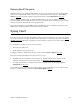
Identifying Fatal Boot Failures
Fatal boot failures can be identified by the light patterns shown by the LEDs on the front panel of the router.
Note: Normal LED states are described in the Hardware Specifications section of the Quick Start Guide.
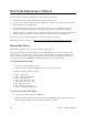
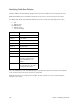
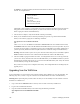
The TEST, LNK, WAN, and LANT LEDs indicate fatal errors according to the following patterns where:
0 Off
G Blinking green
FG Blinking fast
Y Blinking yellow
* On, off, or blinking
Any other combinations of the four LEDs flashing in a regular pattern indicates an internal error. Should this
occur, return the router to the factory for repair or replacement.
Note: Non-fatal errors are not displayed by the LEDs, but they do prompt the system to print explanatory
messages on the console.
Pattern Failure
0-0-0-G CPM failure
0-0-G-0 Timer failure
0-0-G-G Bad FCS
0-G-0-0 DRAM failure
0-G-0-G Interrupt failure
0-G-G-0 SCC failure
Y-0-0-0 CPU step failure
Y-0-0-G Ethernet loop failure
FG-0-0-* Wait stuck in the boot menu;
kernel Þle could be missing
(green LED blinking very
rapidly)
G-0-0-* Green occasionally blinks off (at
10-second intervals). The router
is issuing BootP requests.