
Product specifications

Chapter 4: System Management Efficient Networks
®
Router family
Technical Reference Guide
Page 4-40 Efficient Networks
®
The debugging mode (option #) is available for use primarily when you encounter a
serious problem, in consultation with customer support services.
Identifying Fatal Boot Failures
Fatal boot failures can be identified by the light patterns shown by the LEDs on the
front panel of the router.
Non-fatal errors are not indicated by the LEDs, but they do prompt the system to send
an explanatory message to the console port.
Normal LED states are described in the Hardware Specifications section of the User
Reference Guide. (A copy of the Guide comes with your router and is available on the
web site www.efficient.com.) The normal progression of LED states during startup are
described in “Using LEDs” on page 7-6.
Normally, during ready state, the TEST LED flashes every two seconds. If this normal
“heartbeat” stops, it indicates that the router is locked up and you need to cycle power
to reset it.
Routers with Four LEDs
If your router has four LEDs, the pattern of the three LEDs (except the POWER LED)
may indicate a fatal error.
NOTE:
On some router models, the LINK LED is labeled LAN or RX0/TX0 and/or the WAN
LED is labeled VOICE or RX1/TX1.
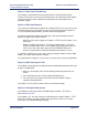
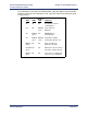
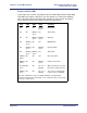
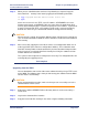
Figure 4-3: Extended Diagnostics Menu
[1] DRAM test
[2] Parity test
[3] POST firmware CRC test
[4] Real-Time Clock chip test
[5] Timers and Interrupts test
[6] Multi-port UART (internal loopback) test
[7] Multi-port HDLC (internal loopback) test
[8] SCC2 External Loopback test
[9] SCC3 External Loopback test
[a] SCC4 External Loopback test
[b] Ethernet Transceiver (internal loopback)
test
[-] Deselect all tests
[+] Select all tests
[.] Run selected tests
[#] Enter debugger
[/] Exit extended diagnostics (reboot)