
User Guide
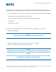
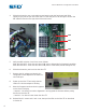


4. Slide the electronics pan out by placing your hands under the front bezel and lifting
slightly as you pull the pan out of the Ultra TT. Slide the pan out far enough to access the
DIP switches found on the right side of the main board.
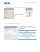
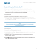
5. Verify that DIP switches 1 and 2 are set as follows:
SW1: Bits 1&2 OFF – Sets front and rear COM ports to 8 data bits for Bluetooth capability
SW2: Bits 1&2 OFF – Sets front and rear COM ports to 115k baud (should already be off)
6. Slide the electronics pan back into the Ultra TT.
7. Remove the AC adapter and attach the
configured Socket adapter to the Ultra TT’s
rear COM port.
8. Power up the Ultra TT and verify that the
LED on the Socket adapter is blinking.
9. Note the firmware version # when it appears
on the Ultra TT display
• Version 1.1 or below: Proceed to Appendix A and upgrade the firmware before pairing
the PDA to the Ultra TT.
• Version 1.2 or above: Power down the Ultra TT.
10. Reinstall the 11 screws and Y-axis cover, then pair the PDA to the Ultra TT as described
in Section III.
8
®
A NORDSON COMPANY
®
A NORDSON COMPANY
Ultra TT Bluetooth
®
Configuration Procedure
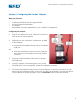
SW2
SW1
SW3