
Installation Guide and Manual
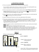
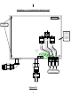
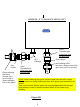
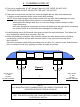
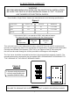
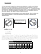
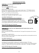
Table Of Contents

III. ELECTRICAL HOOK-UP
WARNING
BEFORE BEGINNING ANY WORK ON THE ELECTRICAL INSTALLATION,
BE SURE THE SWITCH AT MAIN BREAKER PANEL IS “OFF” TO AVOID
ANY DANGER OF ELECTRICAL SHOCK.
“Three Module, Single Phase” heaters are manufactured to the following specifications:
This unit must have its own independent circuits, using 3 SETS of UL listed 2 conductor and
ground core copper wire cable of the appropriate size protected by 3 separate and independent
correctly rated Double Pole Breakers. (220, 240 V, see Figures 4 and 5). Wire entry into
the unit must be made through the 4 holes provided in the flange on the backplate.
The “live” wires should be connected to the slots in the terminal block marked L1 and L2. The
ground lead must be connected to the slot marked GND. GROUND MUST BE BROUGHT TO
THE “GROUND” AT THE CIRCUIT BREAKER PANEL.
DANGER
FAILURE TO GROUND THE SYSTEM MAY RESULT IN DEATH OR SERIOUS INJURY.
* Units rated of 240 V can operate at 208 V with reduced output.
The output will vary in accordance with the following ratios:
208 volts 240 volts
.75 1.0
output ratio
volts
MODEL TYPE OUTPUT / kW VOLTAGE AMPERAGE
EX230 22.5 240 3 x 32 AMPS
EX280 28.0 240 3 x 39 AMPS
SPECIAL
3 Separate and independent
correctly rated Double pole
breakers (208/240 Volts)
Figure 4
Figure 5
7
Circuit Breaker Panel
ONON
OFF
OF
F
ON
OFF
ON
OFF
ONON
OFF
OF
F